Pneumatic tension control device

A technology of tension control and tension roller, which is applied in the direction of transportation and packaging, winding strips, thin material processing, etc., can solve the problems of discontinuity, cumbersome and troublesome adjustment methods, and achieve efficiency, improve variety adaptability and fabric quality effect

Inactive Publication Date: 2015-08-05
CHTC HEAVY IND
View PDF8 Cites 0 Cited by
  • Summary
  • Abstract
  • Description
  • Claims
  • Application Information

AI Technical Summary

Problems solved by technology

[0002] The existing tension control device is to add a counterweight iron under the tension roller. When the yarn ends increase or decrease or the yarn counts vary greatly, the counterweight iron with the appropriate weight is replaced. This adjustment method is cumbersome and troublesome. And discontinuous, directly affect the efficiency of weaving equipment and the quality of fabrics

Method used


Image

  • Pneumatic tension control device
  • Pneumatic tension control device
  • Pneumatic tension control device

Examples


Embodiment Construction

[0015] The present invention will be further described below in conjunction with embodiment (accompanying drawing):

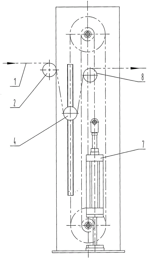
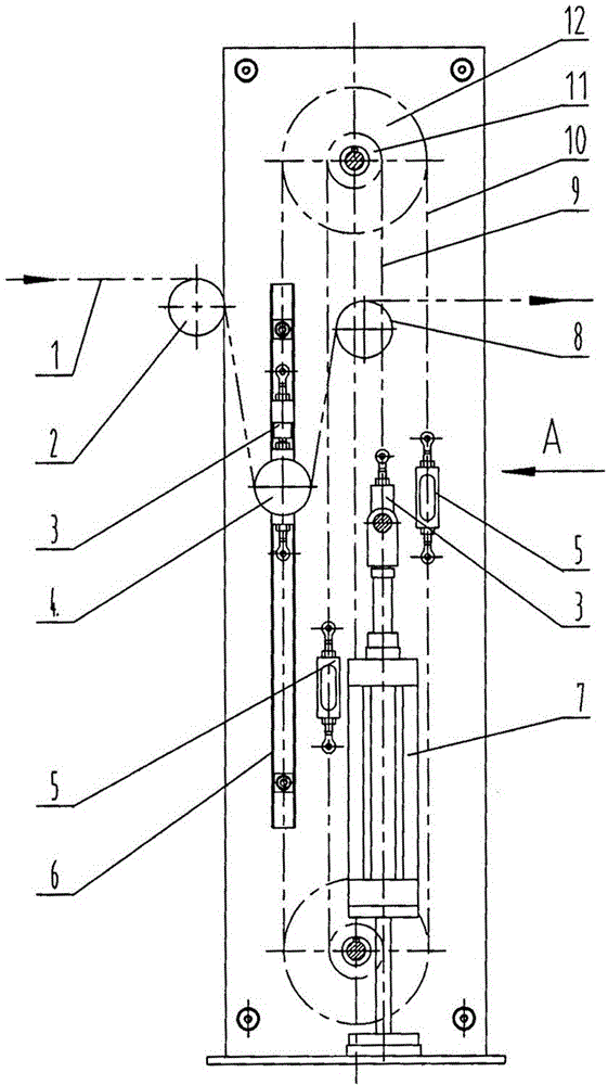
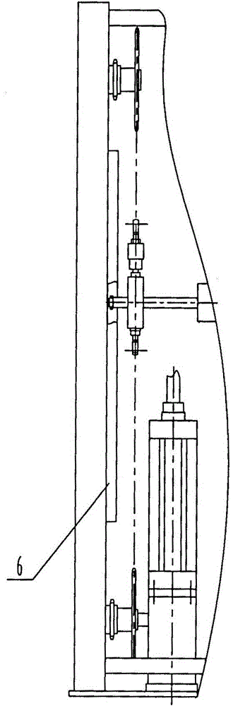
[0016] like figure 2 , 4 As shown, the pneumatic tension control device of the present invention comprises a frame composed of left and right wall panels 13, 19 and upper and lower cross braces 17, and the first guide roller 2 arranged in front of the frame is arranged in a vertical manner. The left and right cylinders 7 installed in the frame, the left and right cylinders 7 are connected with the bottom surface of the left wallboard 13 and the right wallboard 19 through the cylinder base 16 respectively, and the piston rods of the left and right cylinders 7 pass through the cylinder joint 15 is connected with the cylinder synchronous shaft 14, and the two ends of the cylinder synchronous shaft 14 are respectively suspended on the left and right cylinder chains 9 located on both sides of the cylinder synchronous shaft 14 through the chain joints 3 for adjusti...


PUM


Abstract

A pneumatic tension control device comprises a frame, a first yarn guide roller, a left cylinder and a right cylinder. The first yarn guide roller is arranged in front of the frame; the left cylinder and the right cylinder are arranged in the frame; piston rods of the left cylinder and the right cylinder are connected with a cylinder synchronous shaft; two ends of the cylinder synchronous shaft are hung on a left cylinder chain and a right cylinder chain which are located on the bilateral sides of the cylinder synchronous shaft through chain joints respectively; the left cylinder chain and the right cylinder chain and left upper and lower small chain wheels and right upper and lower small chain wheels form a closed cylinder transmission chain; shaft heads which are arranged at two ends of a tension roller are hung on a left tension roller chain and a right tension roller chain through chain joints respectively; the left tension roller chain and the right tension roller chain and left upper and lower large chain wheels and right upper and lower large chain wheels form a closed tension roller transmission chain; the left upper and lower large chain wheels and the right upper and lower large chain wheels and the left upper and lower small chain wheels and the right upper and lower small chain wheels are arranged at two ends of an upper chain wheel synchronous shaft and a lower chain wheel synchronous shaft respectively; the two ends of the upper chain wheel synchronous shaft and the lower chain wheel synchronous shaft are connected with a left wall plate and a right wall plate through bearing seats respectively; a second yarn guide roller is arranged on the posterosuperior potion of the tension roller, under the upper chain wheel synchronous shaft and above the cylinder synchronous shaft; bearing seats which are arranged at two ends of a roller shaft of the second yarn guide roller are connected with the left wall plate and the right wall plate respectively.

Description

technical field [0001] The invention relates to the technical field of textile machinery, in particular to a pneumatic tension control device. Background technique [0002] The existing tension control device is to add a counterweight iron under the tension roller. When the yarn ends increase or decrease or the yarn counts vary greatly, the counterweight iron with the appropriate weight is replaced. This adjustment method is cumbersome and troublesome. And discontinuous, directly affect the efficiency of the weaving equipment and the quality of the fabric. Contents of the invention [0003] The purpose of the present invention is to provide a pneumatic tension control device that can significantly improve the variety adaptability of the tension control device and improve the efficiency of the weaving equipment and the quality of the fabric in view of the shortcomings in the above-mentioned prior art. [0004] The purpose of the present invention is achieved through the fo...

Claims


Application Information

Patent Timeline
Patent Type & Authority Patents(China)
IPC IPC(8): B65H23/26
Inventor 王自豪崔运喜石超伟张棣王凯辉王富生翟秀慧周素利娄建锋张红敏代爱丽张永军
Owner CHTC HEAVY IND
Why Eureka
Try Eureka