Main nozzle structure and weft insertion method of air-jet loom for producing elastic denim

An air-jet loom and main nozzle technology, which is applied in the field of textile processing and manufacturing, can solve the problems of unable to carry weft yarns and easy untwisting of elastic core-spun yarns, and achieve the effects of improving variety adaptability, good product quality and stable operation efficiency.

Inactive Publication Date: 2016-04-06
DONGHUA UNIV
View PDF8 Cites 0 Cited by
  • Summary
  • Abstract
  • Description
  • Claims
  • Application Information

AI Technical Summary

Problems solved by technology

When the elastic yarn is used as the weft yarn, the air pressure should not be too high, otherwise the elastic core-spun yarn is easy to untwist;

Method used


Image

  • Main nozzle structure and weft insertion method of air-jet loom for producing elastic denim
  • Main nozzle structure and weft insertion method of air-jet loom for producing elastic denim
  • Main nozzle structure and weft insertion method of air-jet loom for producing elastic denim

Examples


Embodiment 1

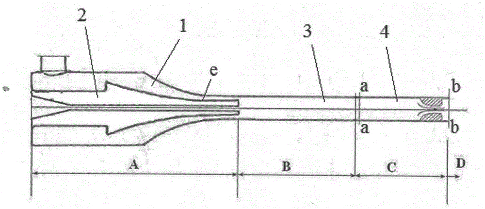
[0028] figure 1 It is a schematic diagram of the main nozzle structure of the air-jet loom used to produce stretch denim provided by the present invention, and the structure of the main nozzle of the air-jet loom used to produce stretch denim includes a nozzle housing 1, a yarn-guiding core 2 and a yarn-guiding Tube. The yarn drawing core 2 is arranged in the nozzle housing 1 . The yarn guiding tube is a split structure and consists of a fixed end 3 and an adjusting end 4 . One end of the fixed end 3 is connected to the yarn-drawing core 2 , and the other end of the fixed end 3 is bonded seamlessly to the adjusting end 4 . figure 1 Among them, a-a shows the connection between the fixed end 3 of the yarn guide tube and the adjustment end 4, and b-b shows the outlet of the yarn guide tube.

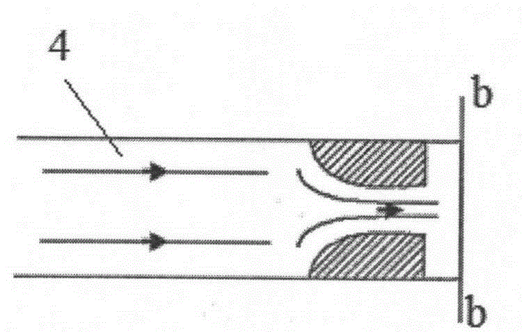
[0029] combine figure 2 , a throat area is formed inside the regulating end of the yarn guide tube, and the outlet of the throat area is the outlet of the yarn guide tube.

[0030] The...

Embodiment 2

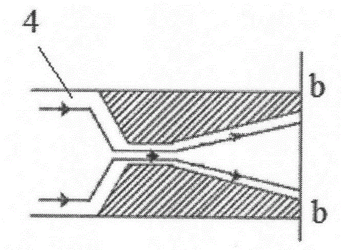
[0045] This embodiment differs from embodiment 1 as image 3 As shown, a throat area is formed inside the regulating end of the yarn guide tube, and behind the throat area there is a gradually expanding tapered area, and the exit of the tapered area is the outlet of the yarn guide tube.

[0046] Due to the high quality of the yarn, a certain amount of air flow is required to carry it, so the present invention also sets a gradually expanding tapered area behind the throat at the exit of the yarn guide tube to increase the air flow at the exit. The invention can make the spandex core-spun yarn not only reduce the possibility of being blown away, but also ensure sufficient speed and air flow at the outlet.

Embodiment 3

[0048] This embodiment differs from embodiment 1 as Figure 4 As shown, a throat area is formed inside the adjusting end of the yarn guide tube, and behind the throat area there is a gradually expanding arc area, and the exit of the arc area is the outlet of the yarn guide tube. The side where the arc area is connected to the throat is a small-diameter arc, and the side of the airflow outlet is a large-diameter arc.

[0049] Due to the high quality of the yarn, a certain amount of air flow is required to bear the load, so the present invention also sets a gradually expanding circular arc area behind the throat at the exit of the yarn guide tube to increase the air flow at the exit. The invention can make the spandex core-spun yarn not only reduce the possibility of being blown away, but also ensure sufficient speed and air flow at the outlet.


PUM


Abstract

The invention provides a main nozzle structure of an air jet loom for producing elastic denim. The main nozzle structure comprises a nozzle shell, a yarn guiding core and a yarn guiding pipe, wherein the yarn guiding core is arranged in the nozzle shell; the yarn guiding pipe is formed by a fixed end and an adjusting end, one end of the fixed end is connected with the yarn guiding core, and the other end of the fixed end is connected with the adjusting end; the main nozzle structure is characterized in that a throat area is formed in the inner part of the adjusting end of the yarn guiding pipe. The invention also provides a weft insertion method of the main nozzle structure of the air jet loom for producing the elastic denim. According to the main nozzle structure of the air jet loom for producing the elastic denim, provided by the invention, the defect in the prior art is overcome, the product quality of the elastic denim which is woven by using the main nozzle structure is good, higher and stable operation efficiency can be obtained by the air jet loom, and the type adaptability of the air jet loom is increased.

Description

technical field [0001] The invention relates to the field of textile processing and manufacturing, in particular to a main nozzle structure of an air-jet loom for producing elastic denim and a weft insertion method thereof. Background technique [0002] In recent years, air-jet looms have become the shuttleless looms with the fastest technological progress and the most active development. The air-jet loom is characterized by the use of a flexible weft carrier—high-speed airflow generated by compressed air to generate friction on the surface of the weft yarn, and pull the weft yarn through the weft fell to complete the weft insertion process. Its advantages of fast speed, high efficiency, high product quality and high level of automation make it the model with the most development potential in the future weaving industry. [0003] Theoretically speaking, the variety of modern air-jet looms has strong adaptability, and light, medium, heavy, low and high special fabrics can be...

Claims


Application Information

Patent Timeline
Patent Type & Authority Patents(China)
IPC IPC(8): D03D47/30
CPCD03D47/30D03D47/3013
Inventor 钱怡薛文良魏孟媛程隆棣张瑞云
Owner DONGHUA UNIV
Why Eureka
Try Eureka