Dust removal device for rubber-plastic cable processing

A technology of dust removal device and cable, which is applied in transportation and packaging, separation of dispersed particles, chemical instruments and methods, etc., can solve the problems of high height, inconvenient replacement, poor fixed structure of filter bags, inconvenient dust removal, etc., so as to improve the dust removal effect and facilitate the Replace and clean, improve the effect of fixed structure

Inactive Publication Date: 2021-02-23
YANGZHOU CHUANGQUN NETWORK TECH CO LTD
View PDF1 Cites 0 Cited by
  • Summary
  • Abstract
  • Description
  • Claims
  • Application Information

AI Technical Summary

Problems solved by technology

[0003] The existing patent (notification number: CN209829821U) is a dust removal device for rubber and plastic cable processing. This patent 1, through the cooperation between the dust removal pipe, exhaust fan, collector, collection barrel, air outlet pipe and filter bag, the dust removal effect is achieved. The purpose is to reduce the dust in the workshop; 2. Through the cooperation between the fixed ring, rubber ring, fixed column, connecting column and pull ring, it is convenient to hang the dust on the inner wall of the collector, and avoid sticking to the inner wall of the collector. The setting of bolts and positioning holes is convenient for fixing the fixed ring; however, the filter bag has a poor fixing structure and is not easy to replace due to its high height. After the airflow passes through the filter bag, it will drive the surrounding dust to float to a wider range. It is not convenient to remove dust inside, and the cable processing is produced by the production line, the effect of a single top and bottom is not good, and due to the difference in the models produced by the production line, the dust density range is different, and its adaptability is poor

Method used


Image

  • Dust removal device for rubber-plastic cable processing
  • Dust removal device for rubber-plastic cable processing
  • Dust removal device for rubber-plastic cable processing

Examples


specific Embodiment 1

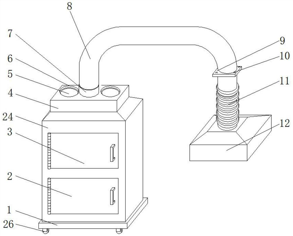
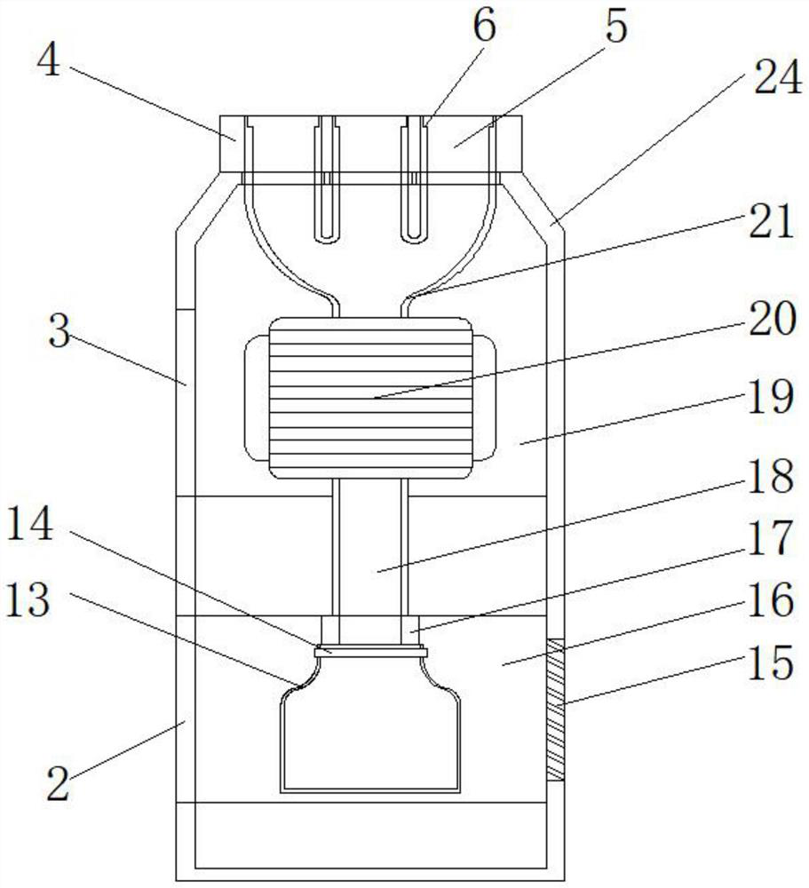
[0028] For specific embodiment 1, please refer to Figure 1-5 , the present invention provides a technical solution: a dust removal device for rubber-plastic cable processing, comprising a frame 24, characterized in that: the inner bottom of the frame 24 is excavated with a first cavity 16, and the top of the frame 24 is excavated with a second cavity 16. cavity 19;

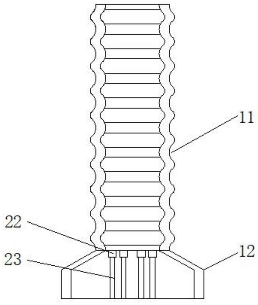
[0029] The top of the frame 24 is integrally formed with a top frame 4, and the top frame 4 is equidistantly excavated with a top-to-bottom penetrating dust cavity 5, and a limit groove 6 is excavated in the dust cavity 5. The limit groove 6. A pipe joint 7 is fastened and fixed inside, the top of the pipe joint 7 is connected with a pipe 8, the other end of the pipe 8 is fixed with a fixed plate 9, and the bottom end of the fixed plate 9 is connected with a corrugated pipe 11. The corrugated pipe The bottom end of 11 is connected with a dust collecting bucket 12, and the top end of the first cavity 16 is connec...

specific Embodiment 2

[0031] see Figure 1-5 , the present invention provides a technical solution: a dust removal device for rubber-plastic cable processing, comprising a frame 24, characterized in that: the inner bottom of the frame 24 is excavated with a first cavity 16, and the top of the frame 24 is excavated with a second cavity 16. cavity 19;

[0032] The top of the frame 24 is integrally formed with a top frame 4, and the top frame 4 is equidistantly excavated with a top-to-bottom penetrating dust cavity 5, and a limit groove 6 is excavated in the dust cavity 5. The limit groove 6. A pipe joint 7 is fastened and fixed inside, the top of the pipe joint 7 is connected with a pipe 8, the other end of the pipe 8 is fixed with a fixed plate 9, and the bottom end of the fixed plate 9 is connected with a corrugated pipe 11. The corrugated pipe The bottom end of 11 is connected with a dust collecting bucket 12, and the top end of the first cavity 16 is connected with a dust removal pipe 17. The ou...

specific Embodiment 3

[0035] see Figure 1-5 , the present invention provides a technical solution: a dust removal device for rubber-plastic cable processing, comprising a frame 24, characterized in that: the inner bottom of the frame 24 is excavated with a first cavity 16, and the top of the frame 24 is excavated with a second cavity 16. cavity 19;

[0036] The top of the frame 24 is integrally formed with a top frame 4, and the top frame 4 is equidistantly excavated with a top-to-bottom penetrating dust cavity 5, and a limit groove 6 is excavated in the dust cavity 5. The limit groove 6. A pipe joint 7 is fastened and fixed inside, the top of the pipe joint 7 is connected with a pipe 8, the other end of the pipe 8 is fixed with a fixed plate 9, and the bottom end of the fixed plate 9 is connected with a corrugated pipe 11. The corrugated pipe The bottom end of 11 is connected with a dust collecting bucket 12, and the top end of the first cavity 16 is connected with a dust removal pipe 17. The ou...


PUM


Abstract

The invention relates to the technical field of rubber-plastic cable processing, and discloses a dust removal device for rubber-plastic cable processing, wherein the device comprises a frame, a firstcavity is dug in the bottom in the frame, and a second cavity is dug in the top of the frame; a top frame is integrally formed at the top end of the frame, dust cavities penetrating from top to bottomare dug in the top frame at equal intervals, limiting grooves are dug in the dust cavities, pipe joints are clamped and fixed in the limiting grooves, and the top ends of the pipe joints are communicated with pipelines. Through the arrangement of the dust cavity, the pipe joints, the exhaust fan, the pipeline, the fixed plate, a corrugated pipe and a dust collecting hopper, the exhaust fan is started through a switch to suck external air, the position of the fixed plate can be adjusted through the fixed plate according to an actual production line device, the height of the dust collecting hopper is adjusted through the corrugated pipe, and the dust collecting hopper is made to be close to the dust concentration position; the dust collection height can be conveniently adjusted according toactual conditions, the dust collection position is close to a dust concentration area favourably, and the dust removal effect is improved.

Description

technical field [0001] The invention relates to the technical field of rubber-plastic cable processing, in particular to a dust removal device for rubber-plastic cable processing. Background technique [0002] Rubber wires mainly refer to the insulating layer and sheath made of natural rubber, styrene-butadiene rubber, ethylene-propylene rubber, etc. In addition to meeting the insulation properties and physical and mechanical properties, they are required to be resistant to aging and wear, and some products require oil resistance and flame retardant. [0003] The existing patent (announcement number: CN209829821U) is a dust removal device for rubber and plastic cable processing. This patent 1. Through the cooperation between the dust removal pipe, the exhaust fan, the collector, the collection barrel, the air outlet pipe and the filter bag, the dust removal is achieved. The purpose is to reduce the dust in the workshop; 2. Through the cooperation between the fixing ring, the...

Claims


Application Information

Patent Timeline
Patent Type & Authority Applications(China)
IPC IPC(8): B01D46/00B01D46/02B01D46/06B01D46/48
CPCB01D46/023B01D46/0041B01D46/06B01D46/48B01D46/62
Inventor 李阳韩思宇乔振扬
Owner YANGZHOU CHUANGQUN NETWORK TECH CO LTD
Why Eureka
Try Eureka