A vacuum glass furnace conveying system

A conveying system and vacuum glass technology, applied in glass transportation equipment, glass forming, glass reshaping, etc., can solve problems such as low production efficiency, many defects, and vulnerability to external forces, and achieve large-scale production and scientific design Ingenious, the effect of reducing the scrap rate

Active Publication Date: 2018-08-14
沃卡姆(山东)真空玻璃科技有限公司
View PDF4 Cites 0 Cited by
  • Summary
  • Abstract
  • Description
  • Claims
  • Application Information

AI Technical Summary

Problems solved by technology

Since the glass frit between the two pieces of glass after assembling has not yet solidified, and the glass frit between the exhaust pipe and the glass has not yet been fixed, external vibration and external force intrusion are very easy to cause the two pieces of glass and the exhaust pipe to shift, and even Glass powder will also produce porosity and cracks, resulting in a decline in the quality of vacuum glass after heating
Therefore, the manual filling of vacuum glass into the furnace currently used has many defects, and the production efficiency is also low, which affects the large-scale production of vacuum glass
[0003] Through searching, we also found devices that use mechanical conveying methods to transport vacuum glass into the furnace, but these devices still generate a lot of vibration and are also vulnerable to external forces, so they cannot really solve the problem

Method used


Image

  • A vacuum glass furnace conveying system
  • A vacuum glass furnace conveying system
  • A vacuum glass furnace conveying system

Examples


Embodiment Construction

[0021] The present invention will be further described in detail below through the specific examples, the following examples are only descriptive, not restrictive, and cannot limit the protection scope of the present invention with this.

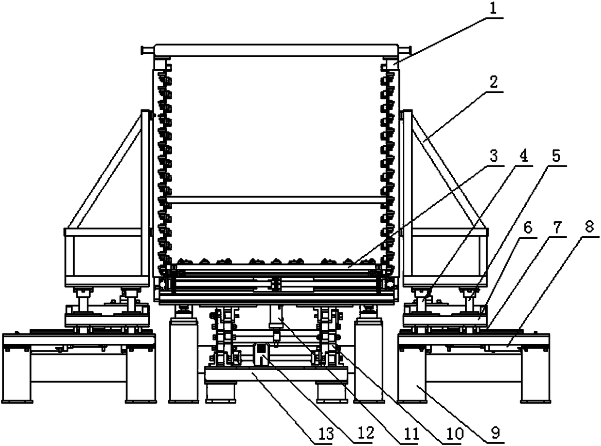
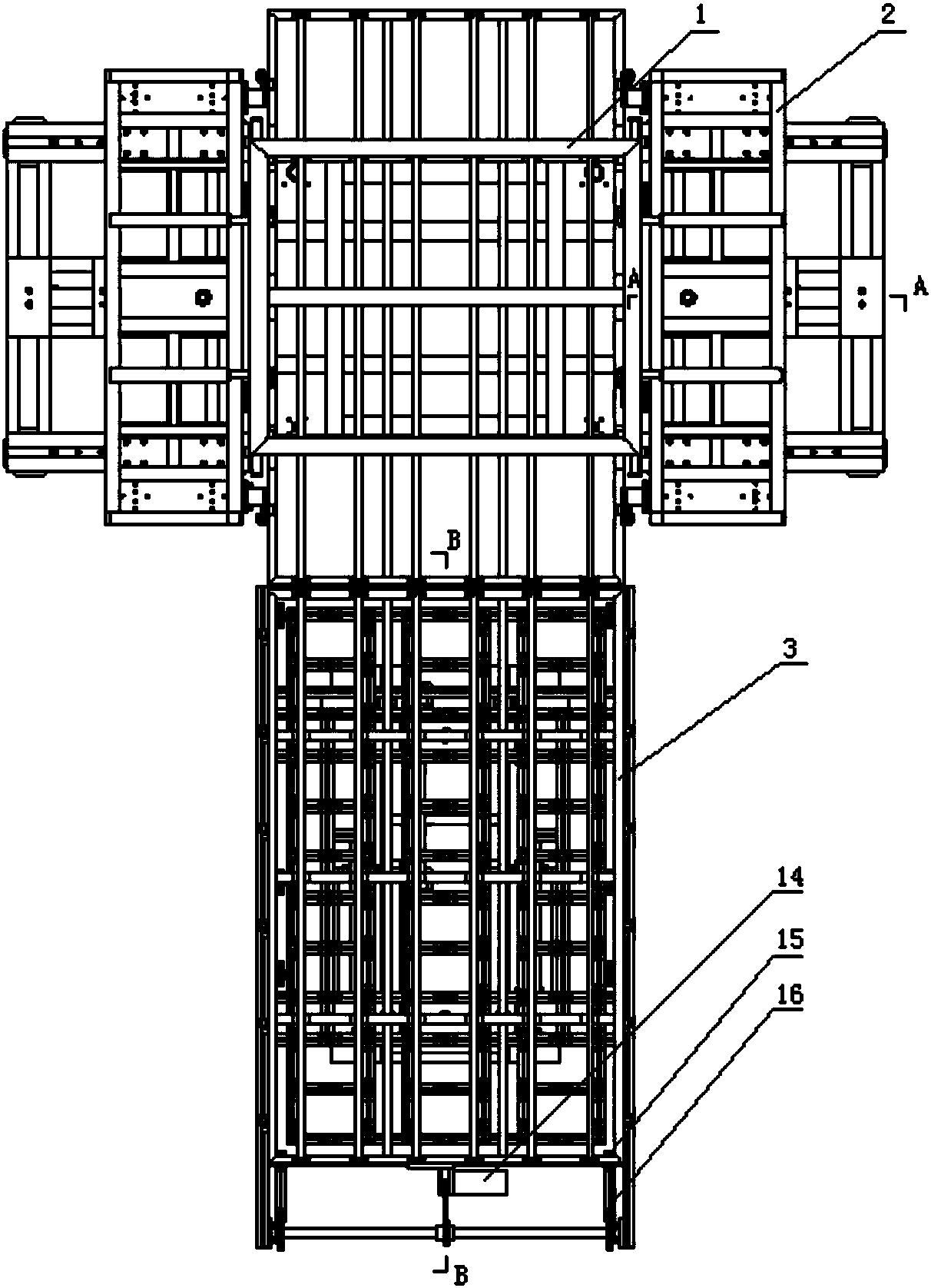
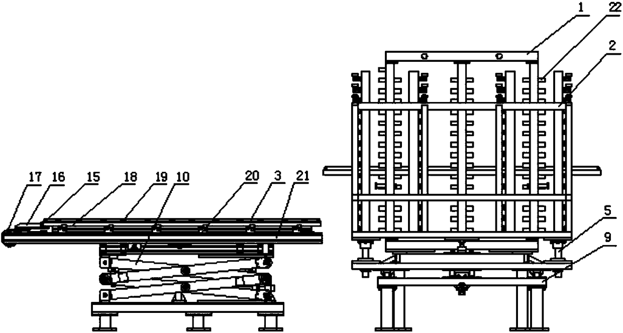
[0022] A furnace conveying system for vacuum glass includes a lifting platform and a furnace feeding frame 1, the lifting platform is located directly in front of the furnace feeding frame.

[0023] The lifting platform includes a basic chassis 13, a folding hinge frame 10, a conveying frame 3 and a universal wheel frame 18, and a folding hinge frame is installed on the basic chassis. , the motor drives the lead screw, and the lead screw rotates to drive the nut fixed on one side of the folding hinge frame to realize the raising and lowering of the folding frame. This mechanism is a prior art, so no details are given in the attached drawings. label. Fixed mount 21 is fixed on the folding frame upper end, and the two sides of this fixed moun...


PUM


Abstract

The invention relates to a vacuum glass delivery-into-furnace conveying system which comprises a lifting platform and a delivery-into-furnace framework, wherein the lifting platform is positioned right ahead of the delivery-into-furnace framework and comprises a base chassis, a folding hinge frame, a conveying framework and a universal wheel frame; the delivery-into-furnace framework is of a framework type structure and is a tetragonal framework structure consisting of a plurality of vertical frames and a plurality of transverse frames; transverse stops are fixedly arranged on the opposite surfaces of the vertical frames which are symmetric on two sides in a mirror image symmetric manner; a side vertical frame is arranged on each of two side edges of the delivery-into-furnace framework in a mirror image symmetric manner; each side vertical frame comprises a bottom frame, a sliding frame and a straight frame. The lifting platform of the system receives vacuum glass through universal wheels; the conveying framework ejects the vacuum glass and conveys the vacuum glass into the delivery-into-furnace framework in a chain wheel push-pull manner; the side vertical frames are arranged on the two sides of the delivery-into-furnace framework in a mirror image symmetric manner. According to the vacuum glass delivery-into-furnace conveying system, the problems of excursion, malposition and looseness and cracking of glass powder which are caused by vibration and outer force of the vacuum glass are solved; the vacuum glass delivery-into-furnace conveying system is a great innovation of an existing vacuum glass manufacturing technology; the foundation is laid for the improvement of the quality of the vacuum glass, the reduction of the rejection rate and implementation of large-scale production of the vacuum glass.

Description

technical field [0001] The invention belongs to the field of vacuum glass, and relates to conveying vacuum glass into a furnace, in particular to a furnace conveying system for vacuum glass. Background technique [0002] The vacuum glass is combined after placing the support to prevent the exhaust pipe, and then smear the glass powder and the glass powder of the exhaust pipe on the four sides after the combination. At this time, the vacuum glass needs to be sent to the heating furnace for heating and edge sealing. Since the glass frit between the two pieces of glass after assembling has not yet solidified, and the glass frit between the exhaust pipe and the glass has not yet been fixed, external vibration and external force intrusion are very easy to cause the two pieces of glass and the exhaust pipe to shift, and even Glass powder will also produce porosity and cracks, resulting in a decrease in the quality of vacuum glass after heating. Therefore, the manual filling of va...

Claims


Application Information

Patent Timeline
Patent Type & Authority Patents(China)
IPC IPC(8): C03B35/00C03B23/24
Inventor 左宪恤
Owner 沃卡姆(山东)真空玻璃科技有限公司
Why Eureka
Try Eureka