Uniform optical reflection method and round LED light source designing method

A LED light source and optical reflection technology, applied in the field of lighting, can solve the problems of high efficiency, poor uniformity, and large thickness of flat lighting, and achieve good reflection effects, good uniformity, and high light rate

Inactive Publication Date: 2014-01-22
SOUTH CHINA NORMAL UNIVERSITY
View PDF3 Cites 3 Cited by
  • Summary
  • Abstract
  • Description
  • Claims
  • Application Information

AI Technical Summary

Problems solved by technology

The application of semiconductor lighting and LED lamps has been widely promoted, especially LED backlights and LED flat lights have a large number of applications, but the planar light emitting technology is not yet fully mature, the main reason is the huge difference between the LED electric light source and the planar light, usually Under normal circumstances, the LED light distribution is Lambertian, and the LED luminous angle is between 90° and 120°. There are two main structural forms of flat lights: one is side-firing type, and the other is direct-firing type, and the side-firing type emits light more uniformly. , but the luminous efficiency is extremely low; the direct-type flat lighting has high efficency, but the thickness is relatively large, and its uniformity is poor compared to high luminous efficacy

Method used


Image

  • Uniform optical reflection method and round LED light source designing method
  • Uniform optical reflection method and round LED light source designing method
  • Uniform optical reflection method and round LED light source designing method

Examples


Embodiment

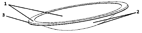
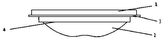
[0031] Such as figure 1 , figure 2 , Figure 4 and Figure 5 , the LED optical reflector 2 is a bowl-shaped structure with flanging, and the inner bottom of its curved reflective surface is provided with a circular protrusion, and the center of the LED light source 4 and the LED optical reflector 2 is located on the same axis .

[0032] The LED optical reflector 2 is connected with a circular frame-shaped mounting bracket 3, the LED light source 4 is arranged on the mounting bracket 3, and a heat sink is arranged on the mounting bracket 3, and the head of the LED light source 4 faces the LED optical The reflector 2 and the front of the LED optical reflector 2 are provided with a light-transmitting toughened glass guard plate 1 .

[0033] The LED light source of the present invention adopts the power type, the working voltage is 3V, the driving current is 350mA, the luminous flux is 100 lumens, and the divergence angle of the light source is 120°. The curved reflective su...


PUM


Abstract

The invention discloses a uniform optical reflection method and a round LED light source designing method. According to the uniform optical reflection method and the round LED light source designing method, a curved reflecting surface and a plane light-out surface are set, an LED light source is arranged between the curved reflecting surface and the plane light-out surface, the positional relation between the curved reflecting surface, the LED light source and the plane light-out surface enables uniform light to be emitted by the plane light-out surface after light emitted by the LED light source is reflected through the curved reflecting surface, the positional relation is set according to a formula, and the LED light source generates a round LED light source through the curved reflecting surface. According to the uniform optical reflection method and the round LED light source designing method, the diffusion film part of the light source is omitted, the light-out rate of the light source is greatly improved, and uniform light emitting is achieved.

Description

technical field [0001] The invention belongs to the field of lighting, and in particular relates to a uniform optical reflection method and a circular LED light source design method. Background technique [0002] Optics and geometric optics and other theories and technologies are very mature and have been widely used in various fields, and the application scope of LED is also expanding. The application of semiconductor lighting and LED lamps has been widely promoted, especially LED backlights and LED flat lights have a large number of applications, but the planar light emitting technology is not yet fully mature, the main reason is the huge difference between the LED electric light source and the planar light, usually Under normal circumstances, the LED light distribution is Lambertian, and the LED luminous angle is between 90° and 120°. There are two main structural forms of flat lights: one is side-firing type, and the other is direct-firing type, and the side-firing type ...

Claims


Application Information

Patent Timeline
Patent Type & Authority Applications(China)
IPC IPC(8): F21V7/09F21V29/00F21Y101/02F21V29/50F21Y115/10
Inventor 孙慧卿杨敏孙浩李旭娜郑欢蔡金鑫赵灵智姜如青欧阳剑
Owner SOUTH CHINA NORMAL UNIVERSITY
Why Eureka
Try Eureka