A throwing impact friction and wear test device

A technology of wear test and impact friction, which is applied in the direction of testing wear resistance, etc., can solve the problem of single test device, and achieve the effect of simple and convenient test operation, compact structure and good anti-friction ability

Active Publication Date: 2015-08-26
SHANDONG KAITAI SHOT BLASTING MACHINERY
View PDF6 Cites 0 Cited by
  • Summary
  • Abstract
  • Description
  • Claims
  • Application Information

AI Technical Summary

Problems solved by technology

At present, the test device for testing impact friction and wear is relatively simple

Method used


Image

  • A throwing impact friction and wear test device
  • A throwing impact friction and wear test device
  • A throwing impact friction and wear test device

Examples


Embodiment Construction

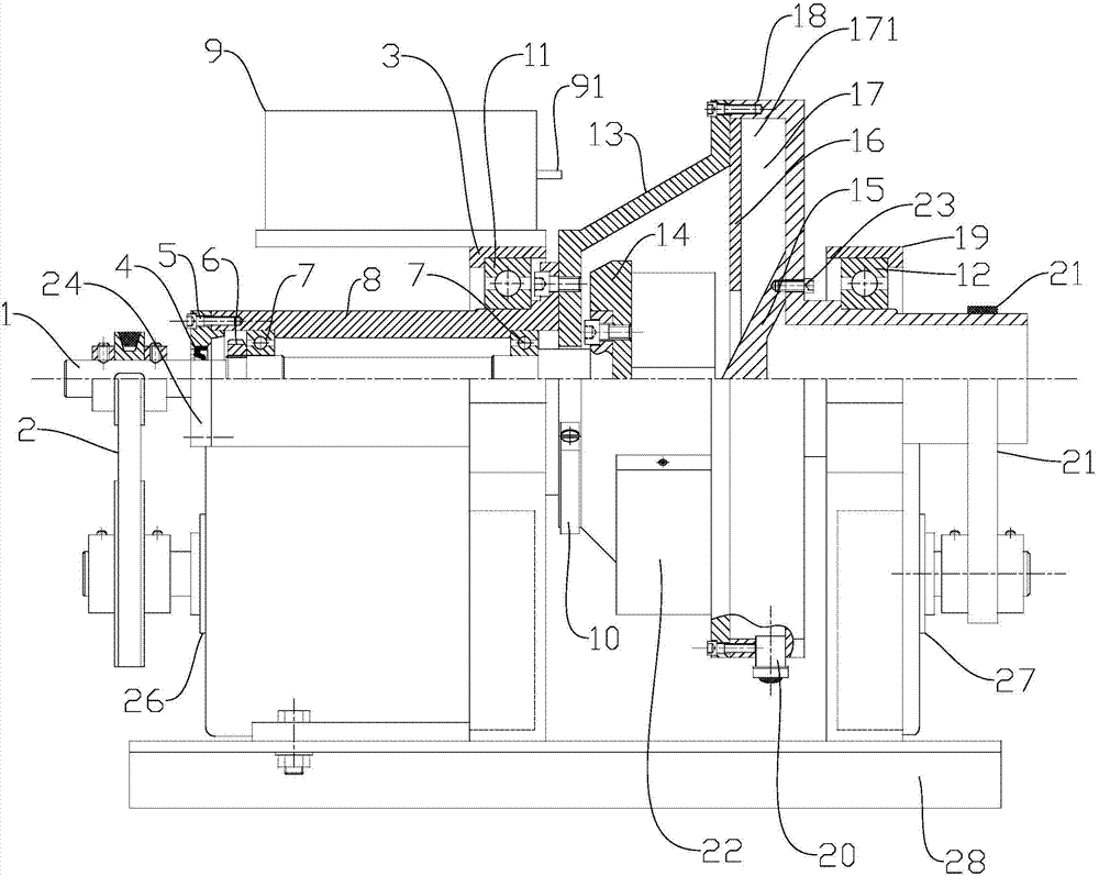
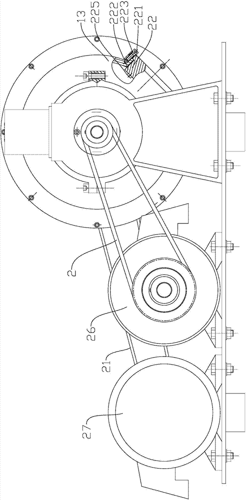
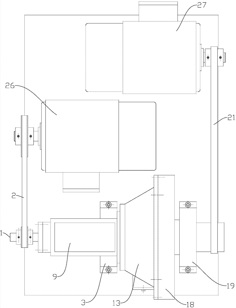
[0043] like figure 1 , 2 , 3, the throwing type impact friction and wear test device mainly includes a main shaft 1, a throwing head 14, a left casing 13, a right casing 18, a first motor 26, a second motor 27, a counter 9, and a guide groove 16 , Guide block 15, left bracket 3, right bracket 19.

[0044] The left end of the main shaft 1 is driven by a first motor 26 through a belt drive; the belt drive here is a V-belt drive 2 . The right end of main shaft 1 is relatively fixedly installed throwing head 14.

[0045] Throwing head 14 comprises connecting portion 141 and protruding portion 142, as Figure 4 , 5 As shown in , 6, the connecting part 141 is connected to the right end of the main shaft 1, and there are two protruding parts 142, and the two protruding parts 142 are arc-shaped plates that rotate along the axis of the main shaft; The blades in the tangential direction are fixed on the first protruding part 142; the throwing head 14 is located in the left housing ...


PUM


Abstract

A throw-beating type impact friction-wear test device comprises a main shaft, a first motor, a ramming head, a left shell body, a sample clamp, a right shell body, a second motor, a guiding groove, a guiding check block, a left bracket, a right bracket, a counter and a counting shift sheet, wherein the first motor drives the main shaft to drive the ramming head to rotate, a sample clamped by the sample clamp is located in the left shell body, the guiding groove is arranged between the left shell body and the right shell body, the guiding check block is arranged in the right shell body, the guiding check block and the guiding groove form a guiding device to convey abrasive materials to the ramming head and recycle the abrasive materials treated with throw-beating, the second motor drives the right shell body to drive the left shell body and a cylindrical shell body to rotate together, the right shell body is made of the right bracket, the cylindrical shell body is made of the left bracket, and the counting shift sheet is arranged on the left shell body. When the shell bodies rotate by a circle, the counting shift shell is in contact with the counter for one time, the counter counts for one circle, and then the number of times of throw-beating of the sample is calculated. The throw-beating type impact friction-wear test device is used for detecting the anti-friction capacity of a workpiece, simple and convenient in operation, and compact in structure, and the abrasive materials can be recycled.

Description

technical field [0001] The invention relates to a friction and wear test device, in particular to a throwing impact friction and wear test device. Background technique [0002] As we all know, friction and wear is a basic type of component failure, and it is also an important reason for the inefficiency of mechanical equipment. Friction and wear are not only the cause of low efficiency of mechanical equipment, but also the main form of equipment failure. The wear of workpieces has become an important reason for the short life of machines. A large part of the world's primary energy consumption is consumed by friction and wear. The friction and wear testing machine is an experimental equipment for evaluating various anti-wear properties and calculating the coefficient of friction. At present, the test device for testing impact friction and wear is relatively simple. Contents of the invention [0003] In order to overcome the above-mentioned shortcomings in the prior art, t...

Claims


Application Information

Patent Timeline
Patent Type & Authority Patents(China)
IPC IPC(8): G01N3/56
Inventor 王守仁王勇杰李计良翟永真韩莹袁存波
Owner SHANDONG KAITAI SHOT BLASTING MACHINERY
Why Eureka
Try Eureka