
A Method of Uniform Distribution of Machining Errors Based on Gradual Change of Tool Attitude

A machining error and cutting tool technology, which is applied in the field of tool path generation where the machining error is uniformly distributed through the gradual change of the tool attitude, can solve the problems of affecting the machining quality and the lack of consistency of the machine tool motion accuracy to the machining error, so as to avoid interference with the non-machined surface , Realize processing error and avoid the effect of over-cutting the processed surface

Active Publication Date: 2016-01-20
BEIHANG UNIV +1
View PDF3 Cites 0 Cited by
  • Summary
  • Abstract
  • Description
  • Claims
  • Application Information

AI Technical Summary

Problems solved by technology

If the profile of the tool is relatively rough, such as the uneven distribution of sand grains on the electroplated grinding wheel, or the cutting edge of the tool is worn, the difference in the attitude of the two tool rails will cause the change of the cutting edge actually participating in the cutting; in addition, the machine tool under different attitudes The position is different, especially the position of the rotary axis, so the impact of the machine tool motion accuracy on the machining error is inconsistent, so there may be "steps" at the position where the two lines of tool rails connect, which seriously affects the processing quality
[0003] Existing CAM software generally adopts a fixed-angle machining method. When machining different areas, it is necessary to determine the attitude angle of the tool based on avoiding overcut and avoiding interference with non-machined surfaces. steps"

Method used


Image

  • A Method of Uniform Distribution of Machining Errors Based on Gradual Change of Tool Attitude
  • A Method of Uniform Distribution of Machining Errors Based on Gradual Change of Tool Attitude
  • A Method of Uniform Distribution of Machining Errors Based on Gradual Change of Tool Attitude

Examples


Embodiment Construction

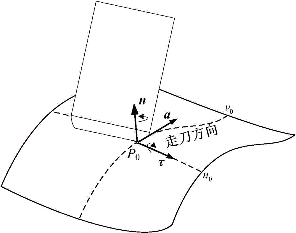
[0048] See Figure 8 , the present invention provides a method for uniform distribution of machining errors based on tool attitude gradients, taking the machining of a blade curved surface as an example, the specific implementation steps are as follows:

[0049] It is assumed that the tool is moved along the direction of the u parameter line, and the direction of the arrangement of the tool path is along the direction of the increase of the parameter v. The parameter domain to be processed on the surface is ((u min ,v min ), (u max ,v max )).

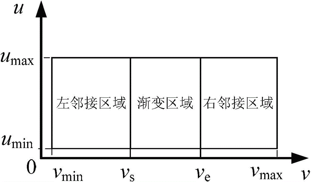
[0050] Step 1: Define a range on the surface as the tool path gradient area. like figure 2 As shown, the processing area of ​​the surface is divided into the tool path gradient area (v s ,v e ) and the left and right adjacent regions (v min ,v s ) and (v s ,v max ).

[0051] Parameter description in this step: u min ,u max ,v min ,v max —The parameter range of the curved surface processing area, which are the minimum a...


PUM


Abstract

The invention relates to a processing error uniform distribution method based on cutter posture gradual change. The method comprises three steps that 1, a range is delimited on a processing curved surface to be used as a cutter posture gradual change region; 2, several lines of cutter paths are sampled in the gradual change region at equal intervals, each line of cutter paths samples the cutter position points in the preset number at equal intervals, each line of cutter paths is calculated, in addition, a cutter angle which does not generate processing surface overcut or non-processing surface interference is determined, and a segmented linear change rule of the cutter angle corresponding to the curved surface parameters is built; 3, the cutter paths are calculated line by line from one end of the gradual change region until the cutter paths cover the whole gradual change region, the initial cutter angle of each line of cutter paths is obtained according to the rule defined in the step 2, and when the cutter generates the processing surface overcut or non-processing surface interference, the avoidance can be realized through regulating the cutter angle. The processing error uniform distribution method has better application prospects in the technical field of metal cutting processing.

Description

technical field [0001] The invention relates to a method for uniformly distributing machining errors based on gradual changes in tool attitude in numerical control machining, and in particular to a method for generating tool tracks that realize uniform distribution of machining errors through gradual changes in tool attitude. It belongs to the technical field of metal cutting processing. Background technique [0002] In the process of curved surface processing, the optimal tool postures in different regions are different, and the large difference in the tool postures of two adjacent tool paths will affect the joint quality of the two tool paths. When the tool posture is basically consistent, the machined surface is relatively smooth and the error distribution is uniform. If the profile of the tool is relatively rough, such as the uneven distribution of sand grains of the electroplated grinding wheel, or the cutting edge of the tool is worn, the difference in the attitude of...

Claims


Application Information

Patent Timeline
Patent Type & Authority Patents(China)
IPC IPC(8): G05B19/404
Inventor 陈志同贺英吴献珍徐义平
Owner BEIHANG UNIV
Learn More