Fire alarm controller loop unit and control method thereof

A fire alarm and controller technology, applied in fire alarms, alarms, instruments, etc., can solve the problems of long alarm time, large number, and high total failure rate, and achieve high signal amplitude, long transmission distance, and low failure rate Effect

Active Publication Date: 2015-12-02
ZHEJIANG EIT ELECTRON
View PDF6 Cites 0 Cited by
  • Summary
  • Abstract
  • Description
  • Claims
  • Application Information

AI Technical Summary

Problems solved by technology

[0006] The present invention aims to solve the problems of large number of multi-wire transmission lines in the prior art, high total failure rate, and long alarm time. The present invention adopts a self-developed digital non-polar two The bus mode, without increasing the baud rate, realizes that even if there are as many as hundreds of detection points uploading fire alarm information in the same inspection cycle, it can also be reported at the same time within 2.1 seconds, which greatly improves Fire Alarm Response Time

Method used


Image

  • Fire alarm controller loop unit and control method thereof
  • Fire alarm controller loop unit and control method thereof
  • Fire alarm controller loop unit and control method thereof

Examples


Embodiment 1

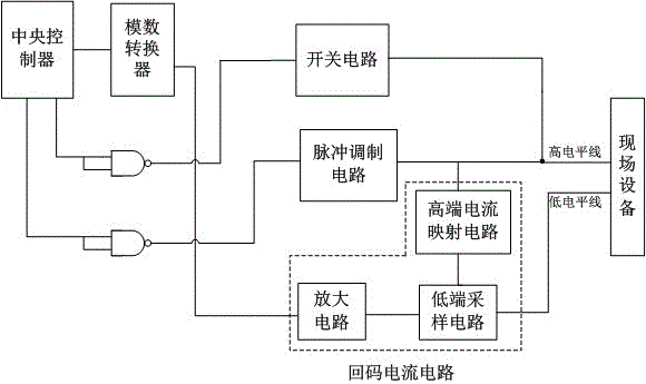
[0049] The circuit unit of the fire alarm controller described in the present invention is figure 1 Including:

[0050] The center controller, sending address pulse signals and command pulse signals, and receiving the digital signals of feedback;

[0051] The switching circuit is connected to the pulse signal of the center controller through the reverse circuit, and connects to the high -power flat line with the secondary bus to send the address pulse signal to the on -site device on the second bus, and provide the working power supply;

[0052] The pulse adjustment circuit is connected to the command pulse signal of the center controller through the reverse circuit, and connects to the high -power flat line with the second bus to send the command pulse signal to the on -site device on the second bus;

[0053] Code current circuit, including high -end current mapping circuits, low -end sampling circuits, and amplifier circuits.The low -power flat line connection of the bus, which ...

Embodiment 2

[0057] On the basis of the Circuit of the Fire Alarm Controller in Example 1, the pulse plastic surgery circuit is also included, which is connected to the switch circuit and pulse modulation circuit.The pulse plastic surgery circuit can avoid the impact of the circuit of the capacity load on the two bus structure, thereby improving the anti -interference of data communication.

Embodiment 3

[0059] On the basis of the fire alarm controller circuit unit described above the above embodiments, it also includes short -circuit detection circuits, which are connected separately from the secondary bus high -power flat line and the modulus converter, and detect the electrical signal of the secondary bus.And enter the modulus converter.

[0060] There is a short -circuit indicator device in the short -circuit detection circuit. Instructions can be made in a timely manner when a short -circuit state occurs, so as to quickly solve the problem of the line problem and avoid the fire in the fire due to failure to maintain the fault.


PUM


Abstract

The present invention relates to a fire alarm controller circuit unit and its control method. The central controller sends address pulse signals and command pulse signals, and receives feedback digital signals; the switch circuit sends address pulse signals to field devices on the second bus, and provide working power; the pulse modulation circuit sends command pulse signals to the field devices on the second bus; the return code current circuit includes a high-end current mapping circuit, a low-end sampling circuit and an amplifying circuit, and the high-end current mapping circuit and the low-end After the circuit is connected, it is connected to the amplifying circuit; the amplifying circuit is connected to the central controller through an analog-to-digital converter. There are as many as hundreds of detection points uploading fire alarm information, which can also be reported at the same time within 2.1 seconds, which greatly improves the response time of fire alarm.

Description

Technical field [0001] The invention involves a alarm controller, which is specifically a fire alarm controller loop unit and its control method, which belongs to the field of fire technology. Background technique [0002] The fire alarm controller is the heart of the automatic fire alarm system, which can supply power to the detector. It has the following functions: 1) used to receive fire signals and start fire alarm devices.The device can also be used to indicate the fire site and record related information.2) Can start the fire alarm signal through the fire alarm sending device or start the automatic fire extinguishing device and the fire -fighting linkage control device through the automatic fire extinguishing control device.3) The correct operation of the automatic monitoring system and the sound of alarm and light alarm on specific faults. [0003] In order to reduce errors, the modern fire alarm controller facilitates installation and debugging, reduces the cost of instal...

Claims


Application Information

Patent Timeline
Patent Type & Authority Patents(China)
IPC IPC(8): G08B17/00G08B25/00
Inventor 陶章亮谢海彬吴金海聂河东林素欧胡中祥周铭
Owner ZHEJIANG EIT ELECTRON
Why Eureka
Try Eureka