Intelligent reflection panel supporting WiFi, manufacturing method and power supply system

A smart, panel-based technology, applied in collectors, photovoltaic power generation, electric vehicles, etc., can solve the problems of reducing the convenience of using smart reflective surfaces, increasing the complexity of solar panel processing, and inconveniently erecting power supply lines, etc., to achieve enhanced wireless coverage Effects of range and signal strength, elimination of power supply lines, ease of mass manufacture and use

Inactive Publication Date: 2022-01-07
SHANGHAI WU QI MICROELECTRONICS CO LTD
View PDF6 Cites 0 Cited by
  • Summary
  • Abstract
  • Description
  • Claims
  • Application Information

AI Technical Summary

Problems solved by technology

Smart reflective panels are usually deployed outdoors, such as building exterior walls, advertising panels and towers, where it is sometimes inconvenient to install power lines
In the smart reflective panel powered by solar energy used in the prior art, the substrate layer of the smart reflective surface is a transparent material, and the ground layer is also an ITO conductive film, and the solar panel is bonded under it, but the following problems still exist: 1. The intelligent reflective surface The dielectric substrate and conductive material are transparent special materials, and there are problems in cost and processing; 2. The size of the smart reflector panel in different usage scenarios is different, which requires the solar panel to have a corresponding size, which increases the processing of solar panels. Complexity; 3. The two are simply bonded together, and the thickness and weight have increased, which reduces the convenience of using the smart reflective surface

Method used


Image

  • Intelligent reflection panel supporting WiFi, manufacturing method and power supply system
  • Intelligent reflection panel supporting WiFi, manufacturing method and power supply system
  • Intelligent reflection panel supporting WiFi, manufacturing method and power supply system

Examples


Embodiment Construction

[0048] The terms "first", "second", "third" and so on are only used for distinguishing descriptions, and do not represent sequence numbers, nor can they be understood as indicating or implying relative importance.

[0049] In addition, the terms "horizontal", "vertical", "overhanging" and the like do not mean that the components are absolutely horizontal or overhanging, but may be slightly inclined. For example, "horizontal" only means that its direction is more horizontal than "vertical", and it does not mean that the structure must be completely horizontal, but can be slightly inclined.

[0050]In the description of the present application, it should be noted that the orientation or positional relationship indicated by the terms "inner", "outer", "left", "right", "upper", "lower" etc. are based on the Orientation or positional relationship, or the orientation or positional relationship that the application product is usually placed in use, is only for the convenience of desc...


PUM


Abstract

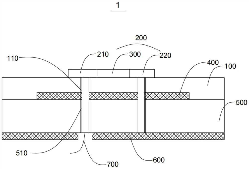
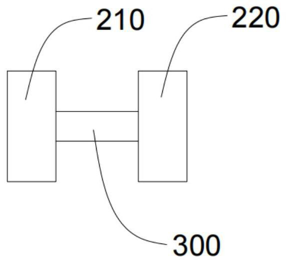
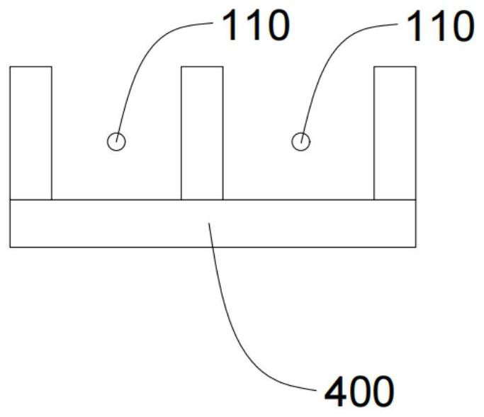
The invention relates to an intelligent reflection panel supporting WiFi, a manufacturing method and a power supply system. The intelligent reflection panel comprises an insulating dielectric layer, a feed electrode and a variable impedance device connected with the feed electrode are arranged above the insulating dielectric layer, and a photovoltaic cell is arranged in the insulating dielectric layer; a photovoltaic PN junction silicon wafer layer is arranged below the insulating dielectric layer; a grounding layer is arranged below the photovoltaic PN junction silicon wafer layer; the insulating dielectric layer is provided with a first via hole; the photovoltaic PN junction silicon wafer layer is provided with a second via hole, and the feed electrode sequentially passes through the first via hole and the second via hole and is connected with the lead. The intelligent reflection panel can realize that reflection of WiFi 6 and WiFi 7 working frequency bands of 5-6GHz electromagnetic waves, 2.4 GHz WiFi or wireless Internet of Things and other frequency bands of electromagnetic waves and photovoltaic cell power supply do not interfere with each other, and electromagnetic compatibility is achieved; the power supply system is high in integration level, convenient to process, easy to manufacture and use on a large scale, convenient to construct and install, energy-saving and environment-friendly.

Description

technical field [0001] The present application relates to the technical field of artificial electromagnetic materials, in particular, to a smart reflective panel supporting WiFi, a manufacturing method and a power supply system. Background technique [0002] With the rapid development of IoT technology, wireless applications such as WiFi and Bluetooth have entered daily life, including virtual reality, distance education medical care, smart city and artificial intelligence. The popularization of these technologies has put forward higher requirements for the transmission rate of wireless networks. With the popularization of WiFi6 technology and the gradual commercialization of WiFi7 technology, wireless communication technology is facing the challenge of providing higher rates for more IOT (Internet of Things) devices, and larger The bandwidth challenge. The traditional wireless communication form, that is, the access point (AP) and the client terminal have encountered a bot...

Claims


Application Information

Patent Timeline
Patent Type & Authority Applications(China)
IPC IPC(8): H01Q15/14H02J7/35
CPCH01Q15/14H01Q15/142H02J7/35Y02E10/56
Inventor 古强薛林
Owner SHANGHAI WU QI MICROELECTRONICS CO LTD
Why Eureka
Try Eureka