Determination method, system and device for connected object of user terminal

A user terminal and object technology, applied in access restriction, network traffic/resource management, electrical components, etc., can solve problems such as backhaul link transmission capacity load mismatch, network congestion, idle transmission resources, etc. Effects of congestion or idling of transport resources

Active Publication Date: 2014-01-22
CHINA MOBILE COMM GRP CO LTD
View PDF3 Cites 11 Cited by
  • Summary
  • Abstract
  • Description
  • Claims
  • Application Information

AI Technical Summary

Problems solved by technology

[0011] Embodiments of the present invention provide a method, system, and device for determining an access object of a user terminal, so as to solve the problem in the prior art that the transmission capacity of the backhaul link does not match the load of the access link, which causes the network Problems with congestion or idle transmission resources

Method used


Image

  • Determination method, system and device for connected object of user terminal
  • Determination method, system and device for connected object of user terminal
  • Determination method, system and device for connected object of user terminal

Examples


Embodiment 1

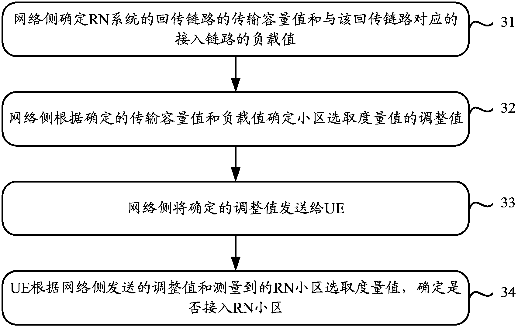
[0046] A typical application flow diagram of this method is shown in Figure 4 shown, including the following steps:

[0047] Step 41, RN starts, when UE1 intends to access the RN system, RN determines the initialized bias, which is bias0, and sends it to UE1;

[0048] Wherein, the implementation manner of determining the initialized bias value by the RN may be: using the bias value in the historical record (for example, the bias value configured for the UE), or randomly selecting a bias value as the initialized bias value.

[0049] Step 42, UE1 measures the cell selection metric value (RSRP1 or RSRQ1) of the Donor eNB, and measures the cell selection metric value (RSRP2 or RSRQ2) of the RN cell;

[0050] Step 43, UE1 determines the cell it accesses and accesses the corresponding cell according to the cell selection metric value of the Donor eNB, the cell selection metric value of the RN, and the bias0 delivered by the RN;

[0051] For example, UE1 compares RSRP1 and RSRP2, ...

Embodiment 2

[0076] Another typical application flow diagram of the method provided by the embodiment of the present invention is as follows: Figure 6 shown, including the following steps:

[0077] Step 61, RN starts, when UE1 intends to access the RN system, RN determines the initialized bias, which is bias0, and sends it to UE1;

[0078] Wherein, the implementation manner of determining the initialized bias value by the RN may be: using the bias value in the historical record (for example, the bias value configured for the UE), or randomly selecting a bias value as the initialized bias value.

[0079] Step 62, UE1 measures the cell selection metric value RSRQ1 of the Donor eNB, and measures the cell selection metric value RSRQ2 of the RN cell;

[0080] Step 63, UE1 determines the cell it accesses and accesses the corresponding cell according to the cell selection metric value of the Donor eNB, the cell selection metric value of the RN, and the bias0 issued by the RN;

[0081] For exam...


PUM


Abstract

The invention discloses a determination method, system and device for a connected object of a user terminal to solve a problem, which exists in the prior art, that because the transmission capacity of a returning link does not match the load of a connected link, networks are congested or transmission resources are in idle. The method includes: a network side determining a transmission capacity value of the returning link of an RN system and a load value of a corresponding connected link; and the network side sending instruction information to the user terminal according to the determined transmission capacity value and load value. The instruction information is used for instructing the user terminal to adjust an RN cell selection metric, which is obtained through measurement, according to a preset RN-cell selection-metric adjustment rule and determining the connected object of the user terminal according to an adjusted RN cell selection metric, wherein, the RN-cell selection-metric adjustment rule is that a difference value, which is obtained by subtracting the load value from the transmission capacity value, is in positive correlation with the adjusted RN-cell selection metric.

Description

technical field [0001] The present invention relates to the technical field of wireless communication, in particular to a method, system and device for determining an access object of a user terminal. Background technique [0002] In order to cope with various complex wireless propagation environments and to solve the coverage problem of future long-term evolution (LTE, Long Time Evolution) network deployment, 3GPP has implemented the functions of relay nodes (RN, Relay Node) in the LTE-Advanced R10 protocol. standardized definition. According to the definition, the function of the RN is mainly reflected in: by adding an RN between the macro base station and the user equipment (UE, User Equipment), the direct transmission link between the macro base station and the UE is divided into two sections. The communication system including the RN can also be called the RN system, where the wireless link between the macro base station and the RN is called the backhaul link (that is,...

Claims


Application Information

Patent Timeline
Patent Type & Authority Applications(China)
IPC IPC(8): H04W28/08H04W48/06
Inventor 刘建军闫渊张翼德胡臻平
Owner CHINA MOBILE COMM GRP CO LTD
Why Eureka
Try Eureka