Universal ZIF (Zero Insertion Force) connector bonding pad

A technology of pads and pad areas, applied in the direction of electrical connection of printed components, printed circuit components, etc., can solve the problems of inability to share, affect production efficiency, and the size of connector pads vary widely, so as to avoid redesign and improve production. Efficiency, cost saving effect

Inactive Publication Date: 2014-01-22
中环高科(天津)股份有限公司
View PDF3 Cites 3 Cited by
  • Summary
  • Abstract
  • Description
  • Claims
  • Application Information

AI Technical Summary

Problems solved by technology

However, due to the different design of the connector by different ZIF connector manufacturers, the pad size of the connector is also very different.
When designing the pads of the ZIF connector, the customer's motherboard can only design special pads according to the special pad size of the connector used, and cannot share them.
If this type of connector encounters difficulties in delivery or other risks and needs to be switched to another type of connector, the only option is to change the size of the connector pads on the main board and redesign the main board, which will bring great harm to material switching. It is inconvenient, and it will also generate a lot of costs such as motherboard mold opening fee, SMT steel mesh fee, and waiting materials, which seriously affects production efficiency

Method used


Image

  • Universal ZIF (Zero Insertion Force) connector bonding pad
  • Universal ZIF (Zero Insertion Force) connector bonding pad

Examples


Embodiment Construction

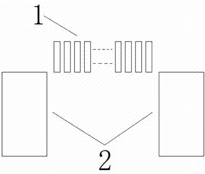
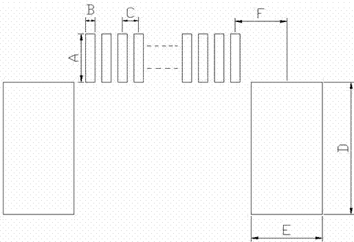
[0009] In order to understand the present invention more clearly, the present invention is described in detail below in conjunction with accompanying drawing: With reference to figure 1 and figure 2 A common ZIF connector pad includes a pin pad area and a fixed pad area, and several pin pads 1 are arranged in the pin pad area (the number of pin pads is determined according to needs, and the pin The number of pads is the same as the number of connector pins to be soldered), and is located on the upper part of the overall pad, and there are two square fixed pads 2 in the fixed pad area, and is located on the lower part of the overall pad, the overall pad Left and right symmetrical; the length A of each pin pad 1 in the pin pad area is set to 1.5mm, the width B is set to 0.3mm, and the center distance C between adjacent pin pads 1 is set to 0.5mm; The length D of the two square fixed pads 2 in the pad area is set to 4.1mm, and the width E is set to 2.2mm; The upper edges of th...


PUM


Abstract

The invention relates to a universal ZIF (Zero Insertion Force) connector bonding pad for connecting a touch screen. The bonding pad comprises a pin bonding pad area and a fixing bonding pad area, wherein a plurality of pin bonding pads are arranged in the pin bonding pad area and are positioned at the upper part of the overall bonding pad; two square fixing bonding pads are arranged in the fixing bonding pad area and are positioned at the lower part of the overall bonding pad; the overall bonding pad is bilaterally symmetrical; each pin bonding pad is 1.5mm in length and 0.3mm in width; the central distance between every two adjacent pin bonding pads is 0.5mm; the two square fixing bonding pads are 4.1mm in length and 2.2mm in width; the lower edge of each pin bonding pad and the upper edges of the two fixing bonding pads are on the same horizontal line; the central distance between the outermost pin bonding pad and the fixing bonding pad on the same side is 1.6mm. Through the adoption of the design, ZIF connectors of different factories can be welded onto the bonding pad; when the ZIF connectors are switched, a mainboard connector bonding pad is prevented from being redesigned and manufactured, so that the cost is saved and the production efficiency is improved.

Description

technical field [0001] The invention relates to the design of a connector pad, in particular to a general ZIF connector pad used for connecting a touch screen. Background technique [0002] With the rapid development of capacitive touch technology, the demand for capacitive touch screens continues to grow, and the substantial increase in shipments has also led to a substantial increase in the demand for ZIF connectors used to connect touch screens. However, due to the different design of the connector by different ZIF connector manufacturers, the pad size of the connector also varies widely. When designing the pads of the ZIF connector, the customer's motherboard can only design special pads according to the special pad size of the connector used, and cannot share them. If this type of connector encounters difficulties in delivery or other risks and needs to be switched to another type of connector, the only option is to change the size of the connector pads on the main boa...

Claims


Application Information

Patent Timeline
Patent Type & Authority Applications(China)
IPC IPC(8): H05K1/11
Inventor 武林马振军邓建懂
Owner 中环高科(天津)股份有限公司
Why Eureka
Try Eureka