tpms tire position automatic positioning method and system

An automatic positioning and tire technology, applied in tire measurement, tire parts, transportation and packaging, etc., can solve the problems of detection errors, inconvenience, and high costs, and achieve the goal of reducing production costs, improving production efficiency, and accurate and reliable positioning structure. Effect

Active Publication Date: 2016-12-07
HUADA AUTOMOTIVE TECH
View PDF5 Cites 0 Cited by
  • Summary
  • Abstract
  • Description
  • Claims
  • Application Information

AI Technical Summary

Problems solved by technology

[0003] At present, TPMS generally identifies the tire position based on the identification code (ID) of the tire pressure sensor module. Therefore, when installing each tire, the identity of the tire pressure sensor module corresponding to the tire must be manually identified after the tire is installed. Enter the code into the central monitor. If you accidentally enter the wrong code, it will cause a detection error
In addition, it is very inconvenient to re-enter the identification code of the tire pressure sensor module when the tire is replaced or the position of the tire is changed in the subsequent maintenance.
Therefore, in the prior art, the controller at the bottom of the vehicle receives the radio frequency signals from the antennas of each wheel, and judges the position of the tires automatically according to the strength of the radio frequency signals. Although this method does not require manual input of identification codes, it is easy to use. Misjudgments are caused by interference, and the error rate is much higher than that of manual input of identification codes, which is unreliable and requires the installation of a controller at the bottom of the vehicle, which is costly

Method used


Image

  • tpms tire position automatic positioning method and system

Examples


Embodiment Construction

[0025] Below in conjunction with accompanying drawing and specific embodiment, the present invention will be further described:

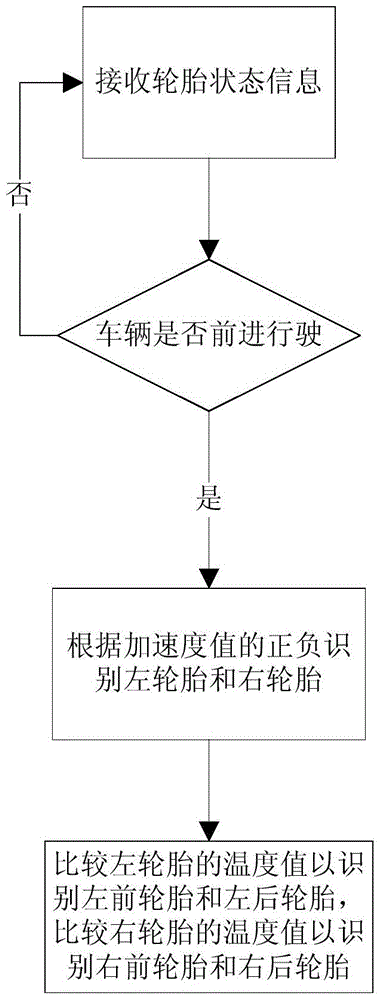
[0026] See figure 1 , the present invention relates to a kind of TPMS tire position automatic positioning method, and its preferred embodiment comprises the following steps:

[0027] Tire status information receiving step: receiving tire status information from each TPMS sensor assembly, each tire status information includes vehicle speed value, acceleration value of each X-axis acceleration sensor, temperature value of each temperature sensor and air pressure value of each air pressure sensor. Wherein, the TPMS sensor assembly includes at least a microprocessor, a temperature sensor, an air pressure sensor, an X-axis acceleration sensor and a radio frequency signal transceiver module, and the installation and connection relationship of each component of the TPMS sensor assembly can be known from the prior art, for example, the In front of the X-ax...


PUM


Abstract

The TPMS tire position automatic positioning method includes the step of receiving tire status information: receiving the tire status information from the sensor assembly; the step of judging the vehicle driving direction: detecting whether the vehicle is moving forward, and if so, performing the step of identifying the left and right tires; if not, performing receiving the tire status information Step; left and right tire identification step: set the tire state information containing the positive acceleration value as the detection information of the left front tire and the left rear tire, and set the tire state information containing the negative acceleration value as the detection information of the right front tire and the right rear tire ; and front and rear tire identification steps: compare the temperature values ​​of the tire status information of the left front and left rear tires to obtain the detection information of the left front and left rear tires respectively; and compare the temperature values ​​of the tire status information of the right front and right rear tires to respectively Obtain the detection information of the right front and right rear tires. The above invention accurately and reliably automatically locates the tire position. The invention also relates to a TPMS tire position automatic positioning system.

Description

technical field [0001] The invention relates to a TPMS tire position automatic positioning method and system. Background technique [0002] TPMS (tire pressure monitoring system, tire pressure monitoring system) is used to monitor the main parameters such as the pressure and temperature of vehicle tires in real time, so as to ensure that the pressure and temperature of tires are maintained within the standard range, and to reduce tire blowouts, The probability of tire damage can reduce fuel consumption and the damage rate of vehicle components. TPMS includes multiple high-sensitivity tire pressure sensor modules installed on each tire, real-time monitoring of tire pressure, temperature and other data in the driving state, and transmits wirelessly to the central monitor included in TPMS, through the The central monitor displays the current tire pressure and temperature, compares them with the set standard pressure value and safe temperature, and sends out corresponding sound...

Claims


Application Information

Patent Timeline
Patent Type & Authority Patents(China)
IPC IPC(8): B60C23/02B60C23/20
Inventor 沈显忠
Owner HUADA AUTOMOTIVE TECH
Why Eureka
Try Eureka