
Vacuum evaporation device

An evaporation and vacuum technology, applied in the directions of vacuum evaporation coating, sputtering coating, ion implantation coating, etc., can solve the problem of uneven coating thickness and achieve the effect of uniform coating thickness and ensuring uniformity

Active Publication Date: 2014-01-29
BOE TECH GRP CO LTD
View PDF4 Cites 15 Cited by
  • Summary
  • Abstract
  • Description
  • Claims
  • Application Information

AI Technical Summary

Problems solved by technology

[0005] The purpose of the present invention is to solve the problem of uneven thickness of the coating film formed by the vacuum evaporation device in the prior art, and to provide a vacuum evaporation device capable of forming uniform thickness

Method used


Image

  • Vacuum evaporation device
  • Vacuum evaporation device
  • Vacuum evaporation device

Examples


Embodiment 1

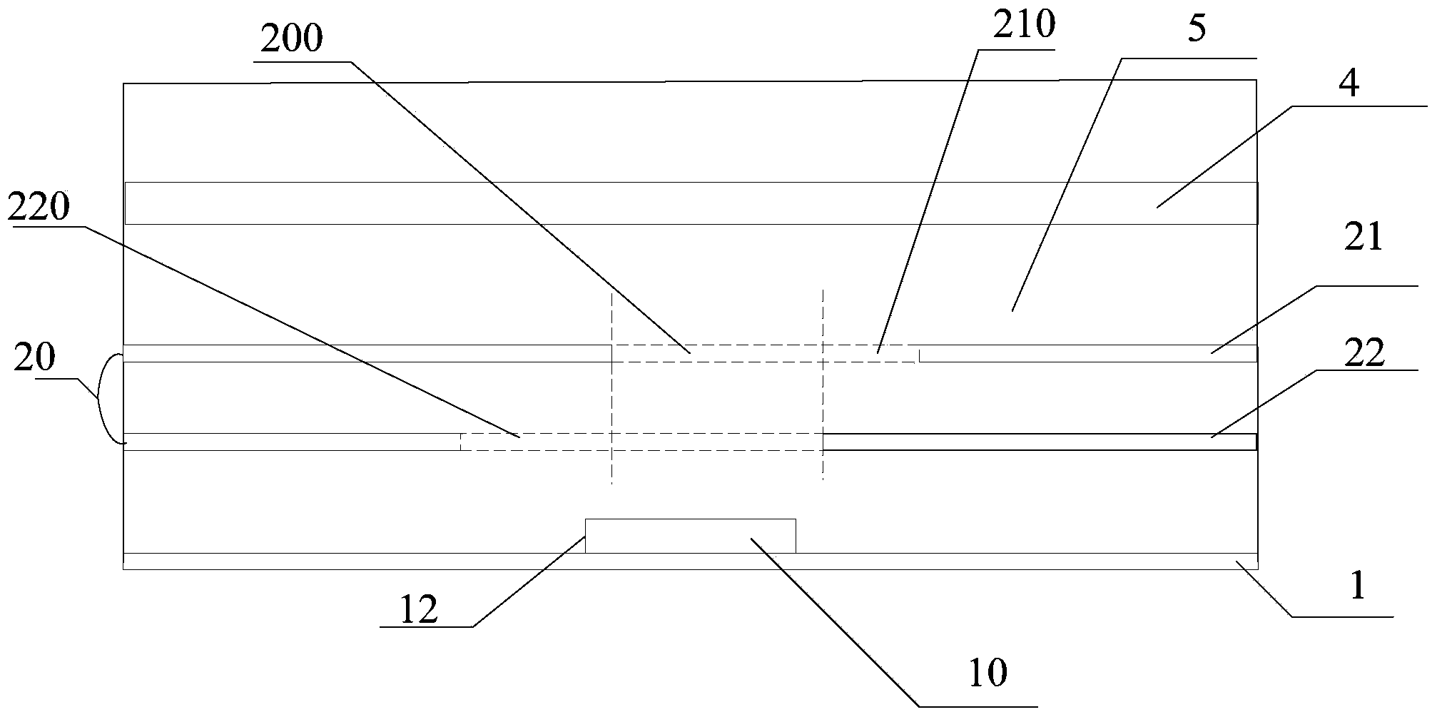
[0035] Such as Figure 3-5 As shown, this embodiment provides a vacuum evaporation device.

[0036] Such as image 3 As shown, the vacuum evaporation device includes an evaporation chamber 5, an evaporation source device 10 arranged in the central area of ​​the bottom plate 1 of the evaporation chamber 5, and a baffle assembly for preventing evaporation substances from contaminating the inner surface of the evaporation chamber 5 20 ; the baffle assembly 20 has a baffle assembly opening 200 corresponding to the position of the evaporation source device 10 .

[0037] The substrate 4 to be evaporated is placed on the upper part of the evaporation chamber 5, and the evaporation material of the evaporation source device 10 is evaporated on the plane of the entire substrate 4 through the opening 200 of the baffle assembly, and the size of the opening 200 of the baffle assembly can prevent evaporation. The substance contaminates the inner surface of the evaporation chamber 5 .

[...


PUM


Abstract

The invention provides a vacuum evaporation device, which belongs to the field of vacuum evaporation and can be used for effectively solving a problem that thickness of a coating film formed by the existing vacuum evaporation device is not uniform. The vacuum evaporation device comprises an evaporation chamber, an evaporation source device arranged in the evaporation chamber, and a baffle plate assembly arranged between the evaporation source device and a to-be-evaporated base plate, wherein the evaporation source device is arranged on the center area of the evaporation chamber; the baffle plate assembly is provided with a baffle plate assembly opening which is corresponding to the position of the evaporation source device and used for passing through evaporated substances. The evaporation source device is arranged on the center area of the bottom plate of the evaporation chamber, and the thickness of the coating film on the base plate is more uniform.

Description

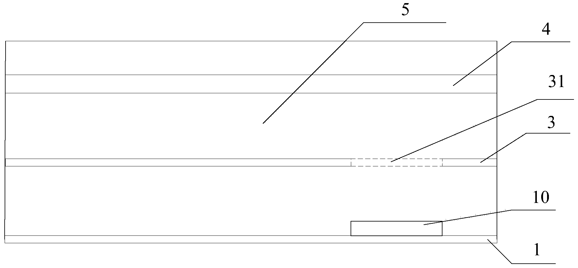
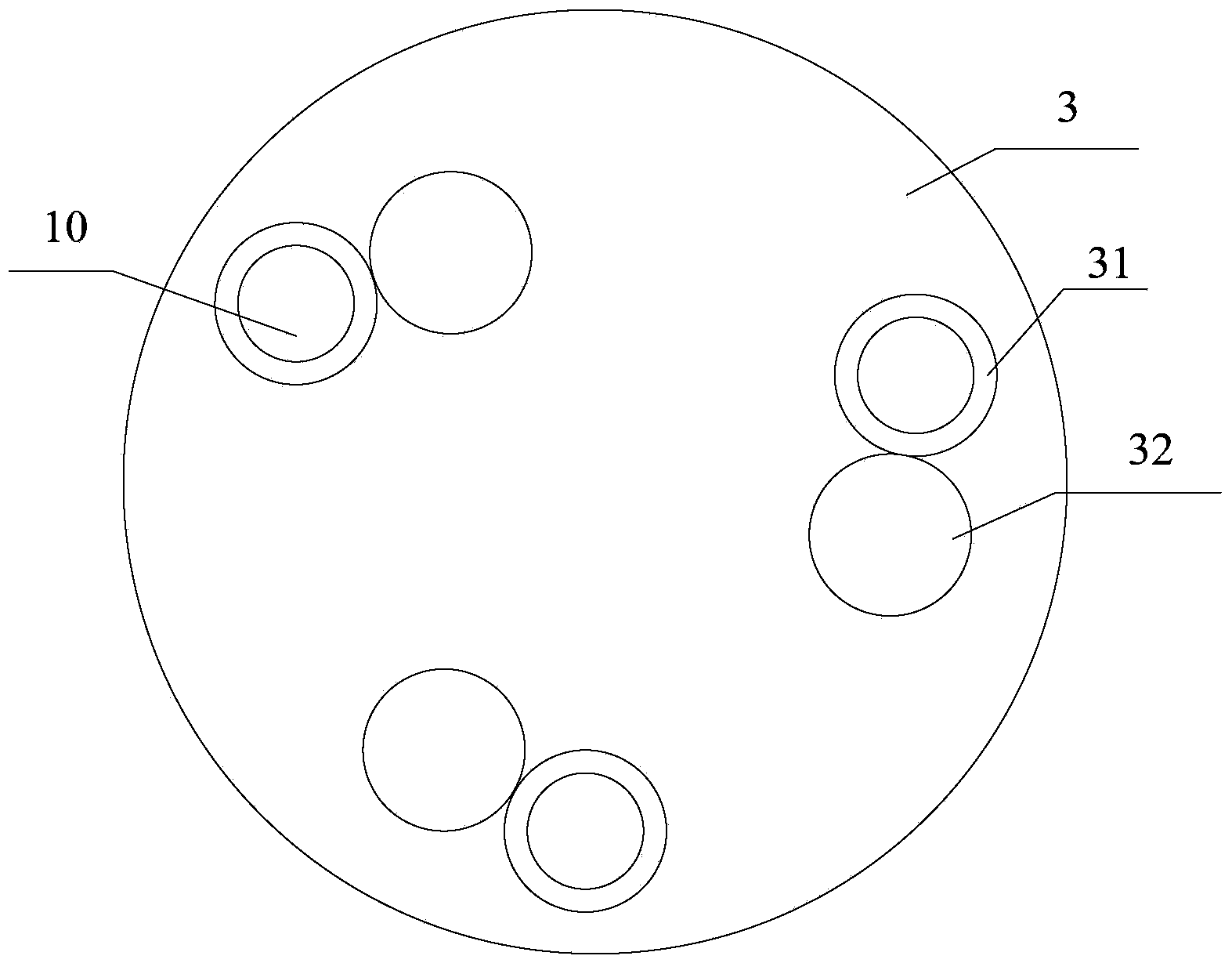
technical field [0001] The invention belongs to the field of vacuum evaporation, and in particular relates to a vacuum evaporation device. Background technique [0002] Such as figure 1 As shown, the vacuum evaporation equipment of the prior art includes an evaporation chamber 5 and a bottom plate 1 positioned at the bottom of the evaporation chamber 5, the substrate 4 to be evaporated is placed on the top of the evaporation chamber 5, and on the bottom of the bottom plate 1 An evaporation source device 10 is provided at the edge, and a baffle 3 is provided in the middle of the evaporation chamber 5, and the baffle opening 31 of the baffle 3 is set corresponding to the evaporation source device 10, and the evaporated material passes through the baffle opening during evaporation. 31 is evaporated on the surface of the substrate 4 . [0003] Such as figure 2 As shown, each baffle opening 31 is provided with a baffle opening cover 32 that can move (rotate) and cover the baf...

Claims


Application Information

Patent Timeline
Patent Type & Authority Applications(China)
IPC IPC(8): C23C14/24
CPCC23C14/24C23C14/044
Inventor 刘则
Owner BOE TECH GRP CO LTD
Learn More