Hybrid energy dissipation vibration damping device

A vibration-damping device and energy-dissipating technology, which is applied to building components and earthquake-proofing, etc., can solve problems such as narrow optimum frequency band, and achieve the effects of increasing the vibration-damping frequency band, clear structure, and simple installation and maintenance

Inactive Publication Date: 2014-01-29
TONGJI UNIV
View PDF5 Cites 6 Cited by
  • Summary
  • Abstract
  • Description
  • Claims
  • Application Information

AI Technical Summary

Problems solved by technology

However, it is an indisputable fact that the optimum frequency band of TMD is narrow

Method used


Image

  • Hybrid energy dissipation vibration damping device
  • Hybrid energy dissipation vibration damping device
  • Hybrid energy dissipation vibration damping device

Examples


Embodiment 1

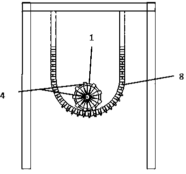
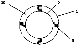
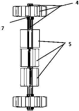
[0024] Example 1: A hybrid energy dissipation and vibration damping device, which is fixed to the main body of the structure in a suspended manner, including an outer tube body 1, an inner tube body 2, a spring 3, a central rotating shaft 4, a blade stirring device 5, and built-in damping The particles 6, the bearing 7, the suspension device 8, and the buffer material 10 between the inner and outer pipes. The inner tube 2 has built-in damping particles, and its internal structure can be modified, such as adding threads to increase the vertical movement of the particles when the cavity rotates, and improve the vibration reduction effect; image 3 , The 4-blade mixing device 5 is composed of three parts, namely the roller, the roller and the blade. The shape of the blades is variable, and can take the shape of four leaves, spiral leaves, etc.; spring 3 is a flexible spring, and when the cavity moves, the spring deforms to cause the internal cavity to vibrate, which intensifies the...

Embodiment 2

[0025] Embodiment 2: A hybrid energy dissipation and vibration damping device, which is fixed to the main structure by a guide rail type, includes an outer tube body 1, an inner tube body 2, a spring 3, a central rotating shaft 4, a blade stirring device 5, and built-in damping particles 6 , Connect the bearing 7, the guide rail and its installation device 9, and the buffer material 10 between the inner and outer pipes. Such as Figure 5 , Image 6 The guide rail is fixed to the main structure by bolts. The two ends of the central shaft 4 are placed on the guide rail. When the structure responds, the central shaft 4 drives the inner and outer pipes to roll along the guide rail, thereby driving the rotation of the blades in the pipe and the friction rolling of the damping particles. The rail-type implementation is the same as the first embodiment except that the rail and its installation device 9 are used instead of the suspension device 8.


PUM


Abstract

The invention relates to a hybrid energy dissipation vibration damping device which comprises an inner-layer tube body, an outer-layer tube body, a buffering material, damping particles, a center rotary shaft, a spring, a connection bearing, a hanging device, a guide rail and an installation device of the guide rail, wherein the buffering material is arranged between the inner-layer tube body and the outer-layer tube body, the damping particles are arranged in the inner-layer tube body, and the center rotary shaft is provided with stirring blades. The inner-layer tube body is connected with the outer-layer tube body through the spring and connected with the center rotary shaft through the connection bearing. A damper is connected with a structure through the hanging device or the guide rail and the relevant devices, the stirring blades are driven to rotate around the center rotary shaft by means of rotation and rolling of the pipe bodies, and friction rolling of the damping particles in the cavity of the inner-layer tube body is aggravated. By utilizing various hybrid energy dissipation mechanisms including solid phase collision and friction energy dissipation, vibration response energy dissipation of quality blocks and the like, the hybrid energy dissipation vibration damping device has great advantages compared with vibration damping devices adopting the single energy dissipation principle.

Description

Technical field [0001] The invention belongs to the technical field of energy dissipation and vibration reduction, and relates to a hybrid energy dissipation and vibration reduction device, belonging to the field of vibration control of civil structures (including high-rise buildings, high-rise structures, bridge structures, etc.). Background technique [0002] A damper is a device that provides resistance to movement and consumes movement energy. The use of damping to absorb energy and shock is not a new technology. Various dampers (or shock absorbers) have been used to reduce vibration and energy in aerospace, aviation, military, guns, and automobiles. Since the 1970s, people have gradually transferred these technologies to structural projects such as buildings, bridges, and railways, and their development has been very rapid. In particular, the hydraulic viscous damper, which has a history of more than 50 years, has undergone a large number of experiments, rigorous review, re...

Claims


Application Information

Patent Timeline
Patent Type & Authority Applications(China)
IPC IPC(8): E04B1/98
Inventor 李培振张丛嘉刘烨张泽楠鲁正
Owner TONGJI UNIV
Why Eureka
Try Eureka