Ammonia storage control

A storage capacity, engine technology, applied in the direction of electrical control, control device, engine control, etc., can solve the problem of increased NOx emissions

Inactive Publication Date: 2014-01-29
FORD GLOBAL TECH LLC
View PDF4 Cites 4 Cited by
  • Summary
  • Abstract
  • Description
  • Claims
  • Application Information

AI Technical Summary

Problems solved by technology

Ammonia slip in turn leads to increased NOx emissions to the surrounding environment

Method used


Image

  • Ammonia storage control
  • Ammonia storage control
  • Ammonia storage control

Examples


Embodiment Construction

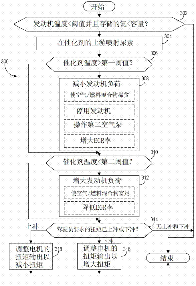
[0016] In some internal combustion engines, urea is introduced upstream of the catalyst and it is converted to ammonia in the presence of sufficient temperature. Ammonia is used as a reducing agent (eg, reducing agent) to facilitate the conversion of NOx to other compounds at the catalyst. However, several challenges arise in this approach. Because the conversion of urea to ammonia does not occur when the ambient temperature is not high enough, this conversion cannot occur at certain times of engine operation (eg, cold start). To compensate, ammonia can be stored in the catalyst and used when conversion is not possible. However, precise control of exhaust temperature and catalyst temperature is required to ensure adequate NOx conversion and that these temperatures do not exceed levels at which ammonia is released into the ambient environment (e.g. ammonia slip).

[0017] Various methods are provided to control the level of ammonia stored in the catalyst by controlling the te...


PUM


Abstract

Various methods for controlling ammonia levels stored in a catalyst by controlling exhaust gas temperatures are provided. In one embodiment, a temperature of a catalyst in an internal combustion engine is determined. If the temperature of the catalyst exceeds a first threshold at which an ammonia capacity of the catalyst for the temperature is below a current stored ammonia level in the catalyst, a load of the engine is reduced including adjusting a torque output of a motor operatively coupled to the engine.

Description

[0001] Cross References to Related Applications [0002] This application claims priority from German Patent Application No. 102012212051.3 filed on July 11, 2012, the entire content of which is hereby incorporated by reference for all purposes. technical field [0003] The present invention relates to a method of controlling the level of ammonia stored in a catalyst of an internal combustion engine (ICE). Background technique [0004] Internal combustion engines may include one or more catalysts configured to reduce the level of emissions produced during the combustion of fuel. For example, selective catalytic reduction (SCR) catalysts can be used to reduce the levels of nitrogen oxides (NOx) emitted after fuel combustion. SCR catalysts may use one or more reducing agents to enhance NOx conversion, such as ammonia. For a given temperature, the SCR catalyst has a storage capacity that determines the level of reductant that can be stored in the catalyst. Exhaust temperatur...

Claims


Application Information

Patent Timeline
Patent Type & Authority Applications(China)
IPC IPC(8): F01N3/20F01N9/00F02D43/00
CPCF02B37/18B60W20/1082F02D41/005F02D2041/026F01N3/2066F02D41/0235Y02T10/24Y02T10/26F02D17/02F02D41/0245F01N3/32F02D2041/0265B60K31/18B60W10/06B60W10/08B60W2510/068B60W2710/0622B60W20/16F02D29/02Y02T10/12Y02T10/62Y02A50/20
Inventor Y·M·S·雅库伯
Owner FORD GLOBAL TECH LLC
Why Eureka
Try Eureka