Annular shaft-valve simultaneous rotation system

A technology of synchronous rotation and shaft valves, applied in the direction of charging system, exhaust gas recirculation, adding non-fuel substances to fuel, etc., can solve the problems of complex control system and achieve the effect of reasonable design and simple structure

Inactive Publication Date: 2014-01-29
SHANGHAI JIAO TONG UNIV
View PDF6 Cites 0 Cited by
  • Summary
  • Abstract
  • Description
  • Claims
  • Application Information

AI Technical Summary

Problems solved by technology

[0003] After searching the existing technical literature, it is found that Chinese patent number ZL200410063439.5, patent name: electronic exhaust gas recirculation gas control device, this patent technology provides a device for controlling the exhaust gas recirculation rate of the engine, which can better Taking into account the medium and high speed conditions of the engine; but the change of the exhaust gas recirculation rate is realized through a special control structure, which makes the control system more complicated

Method used


Image

  • Annular shaft-valve simultaneous rotation system
  • Annular shaft-valve simultaneous rotation system
  • Annular shaft-valve simultaneous rotation system

Examples


Embodiment

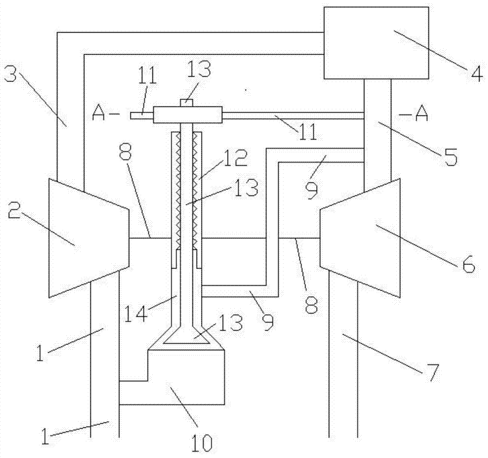
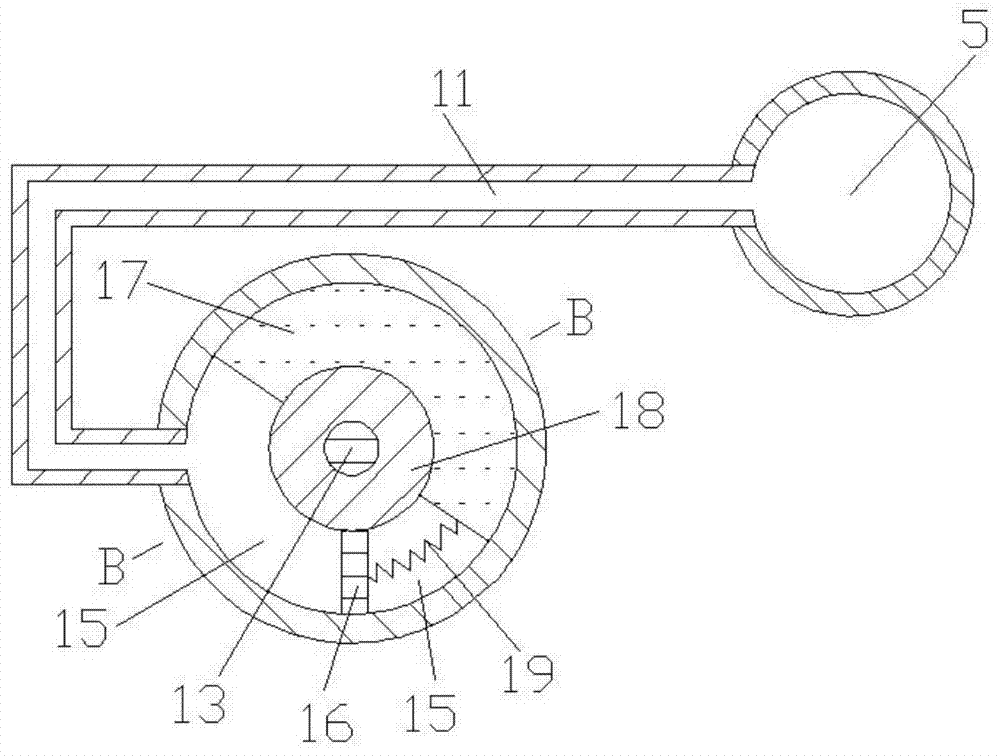
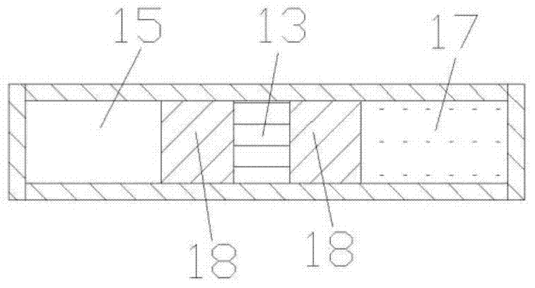
[0015] Such as Figure 1 to Figure 3 Shown, the present invention comprises compressor intake pipe 1, compressor 2, engine intake pipe 3, engine 4, engine exhaust pipe 5, turbine 6, turbine exhaust pipe 7, connecting shaft 8, first connecting pipe 9, the first The second connecting pipe 10, the third connecting pipe 11, the valve seat 12, the valve body 13, the volume chamber 15, the partition plate 16, the rotating body 17, the rotating shaft 18 and the elastic member 19, the air inlet and outlet of the compressor 2 are connected with the air inlet of the compressor respectively. The air outlet of trachea 1 is connected with the air inlet of engine intake pipe 3, the air inlet and outlet of engine 4 are connected with the air outlet of engine air inlet pipe 3 and the air inlet of engine exhaust pipe 5 respectively, and the air inlet and outlet of turbine 6 are respectively It is connected with the air outlet of the engine exhaust pipe 5 and the air inlet of the turbine exhaus...


PUM


Abstract

The invention discloses an annular shaft-valve simultaneous rotation system and belongs to the technical field of mechanical design. The annular shaft-valve simultaneous rotation system comprises a gas compressor, an engine, a turbine, a connecting tube, a valve seat, a valve body, a rotary shaft, a volume chamber, a rotary body and an elastic component, wherein the rotary body is installed in the volume chamber and is in sealing contact with the inner wall surface of the volume chamber, the right wall surface of a partition board is connected with the rotary body through the elastic component, the two ends of a first connecting tube are communicated with an exhaust tube of the engine and a gas inlet of the volume chamber respectively, and the two ends of a third connecting tube are communicated with the exhaust tube of the engine and the volume chamber on the left side of the partition board respectively. When the pressure of the exhaust tube of the engine is high, the rotary body drives the valve body to rotate clockwise, the exhaust recycling rate of the engine is high, and the detonation pressure of the engine is low. When the pressure of the exhaust tube of the engine is low, the rotary body drives the valve body to rotate anticlockwise, the exhaust recycling rate of the engine is low, and the oil consumption of the engine is low. The annular shaft-valve simultaneous rotation system is reasonable in design, simple in structure, and suitable for an exhaust recycling system of a supercharged engine.

Description

technical field [0001] The invention relates to an exhaust gas recirculation system in the technical field of mechanical design, in particular to a ring type shaft valve synchronous rotation system. Background technique [0002] Harmful emissions from engines are a major source of air pollution. With the increasing importance of environmental protection, the goal of reducing harmful emissions from engines has become an important direction for engine development in the world today. With the world's consumption of petroleum products increasing year by year, international oil prices remain high, and the economy of diesel vehicles is becoming more and more prominent, which makes diesel engines occupy an increasingly important position in vehicle power. Therefore, it is the primary task of diesel engine designers to carry out research on the control methods of harmful emissions from diesel engines. Exhaust gas recirculation system is to send a small part of the exhaust gas produ...

Claims


Application Information

Patent Timeline
Patent Type & Authority Applications(China)
IPC IPC(8): F02D21/08F02M25/07F02M26/65
CPCY02T10/121Y02T10/12
Inventor 韦红雨
Owner SHANGHAI JIAO TONG UNIV
Why Eureka
Try Eureka