Swivel nut combination unit

A combined unit and rotating nut technology, applied in the direction of belts/chains/gears, mechanical equipment, transmission devices, etc., can solve the problem that the rotation transmission mode of the screw cannot meet the design requirements of the machine tool, so as to save design, reduce the moment of inertia, improve The effect of limit speed

Inactive Publication Date: 2014-01-29
NANJING TECHN EQUIP MFG
View PDF4 Cites 6 Cited by
  • Summary
  • Abstract
  • Description
  • Claims
  • Application Information

AI Technical Summary

Problems solved by technology

When the length of the ball screw pair exceeds a certain value (such as 6 meters), the traditional screw rotation transmission method cannot meet the design requirements of the machine tool due to the deflection, inertia, and limit speed caused by the screw itself.

Method used


Image

  • Swivel nut combination unit

Examples


Embodiment Construction

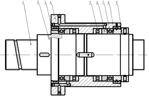
[0011] The rotating nut combination unit includes a ball screw 1, a rolling nut 2, a rolling bearing and a housing. The ball nut 2 is screwed with the ball screw 1. The housing 4 is covered outside the rolling nut by the rolling bearing. When the rolling screw 1 rotates, the ball nut Drive the housing to move linearly along the axial direction of the ball screw 1. The end of the ball nut 2 is provided with a preload adjusting device and a dustproof device 3 . The preload adjusting device is composed of spacer ring 6, spacer sleeve 8 and radial lock nut 9 nuts. Rolling bearings include deep groove ball bearings 7 and thrust roller bearings 5 ​​.

[0012] The present invention directly installs the bearing outside the ball nut pair, which saves the design of the transition sleeve and greatly reduces the radial dimension. The ball screw is fixed in place. The driving motor drives the ball nut pair to rotate and move linearly along the raceway. Thereby driving the housing to m...


PUM


Abstract

The invention relates to a ball screen pair, in particular to a swivel nut combination unit applied to the field of long-range high-speed heavy load. The swivel nut combination unit comprises a ball screw, a ball nut, a ball bearing and a shell. The ball nut is connected with the ball screw in a threaded manner. The shell covers the ball nut through the ball bearing. When the ball screw rotates, the ball nut drives the shell to axially and linearly move along the ball screw. The bearing is directly mounted outside the ball nut pair, the design of a transition sleeve is omitted, and the radial size is reduced greatly; the ball screw is immobilized; a drive motor drives the ball nut pair to rotate and linearly move along a raceway so that the shell is driven to linearly move; the screw is fixed, rotational inertia of a mechanical motion system is reduced greatly, and limit speed of the system is increased; the swivel nut combination unit is easy for high speed transmission and most applicable to the field of long-range high speed motion.

Description

technical field [0001] The invention relates to a ball screw pair, in particular to a rotating nut combination unit suitable for long-stroke, high-speed and heavy-duty fields. Background technique [0002] With the continuous upgrading of machine tool manufacturers' products, the proportion of large-scale high-precision products is increasing. As a supporting ball screw pair for CNC machine tools, it is inevitable to develop into large, ultra-long and high-precision. The working mode of the traditional ball screw pair is that the screw rotates and the nut moves linearly. When the length of the ball screw pair exceeds a certain value (such as 6 meters), the traditional screw rotation transmission method cannot meet the design requirements of the machine tool due to the deflection, inertia, limit speed and other problems caused by the self-weight of the screw itself. Contents of the invention [0003] In order to overcome the problems existing in the prior art, the purpose...

Claims


Application Information

Patent Timeline
Patent Type & Authority Applications(China)
IPC IPC(8): F16H25/22
CPCF16H25/2204F16H25/2418F16H2025/2436
Inventor 冯宇张勤李小春张海栋薛宏伟
Owner NANJING TECHN EQUIP MFG
Why Eureka
Try Eureka