Unlock instant, AI-driven research and patent intelligence for your innovation.
Refrigerating device with storage unit
What is Al technical title?
Al technical title is built by PatSnap Al team. It summarizes the technical point description of the patent document.
A technology for storage units and refrigerating appliances, which is applied in the field of low-pressure storage units and refrigerating appliances such as refrigerators, and can solve problems such as large stress and damage to plastic boxes
Active Publication Date: 2014-01-29
BSH ELECTRICAL APPLIANCES JIANGSU
View PDF7 Cites 0 Cited by
Summary
Abstract
Description
Claims
Application Information
AI Technical Summary
This helps you quickly interpret patents by identifying the three key elements:
Problems solved by technology
Method used
Benefits of technology
Problems solved by technology
Due to different material properties, there will be a large stress between the plastic box body and the metal reinforcement plate with a large gap, which may even damage the plastic box body
Method used
Image
Click on the blue label to locate the original text in one second.
Reading with bidirectional positioning of images and text.
Examples
Embodiment Construction
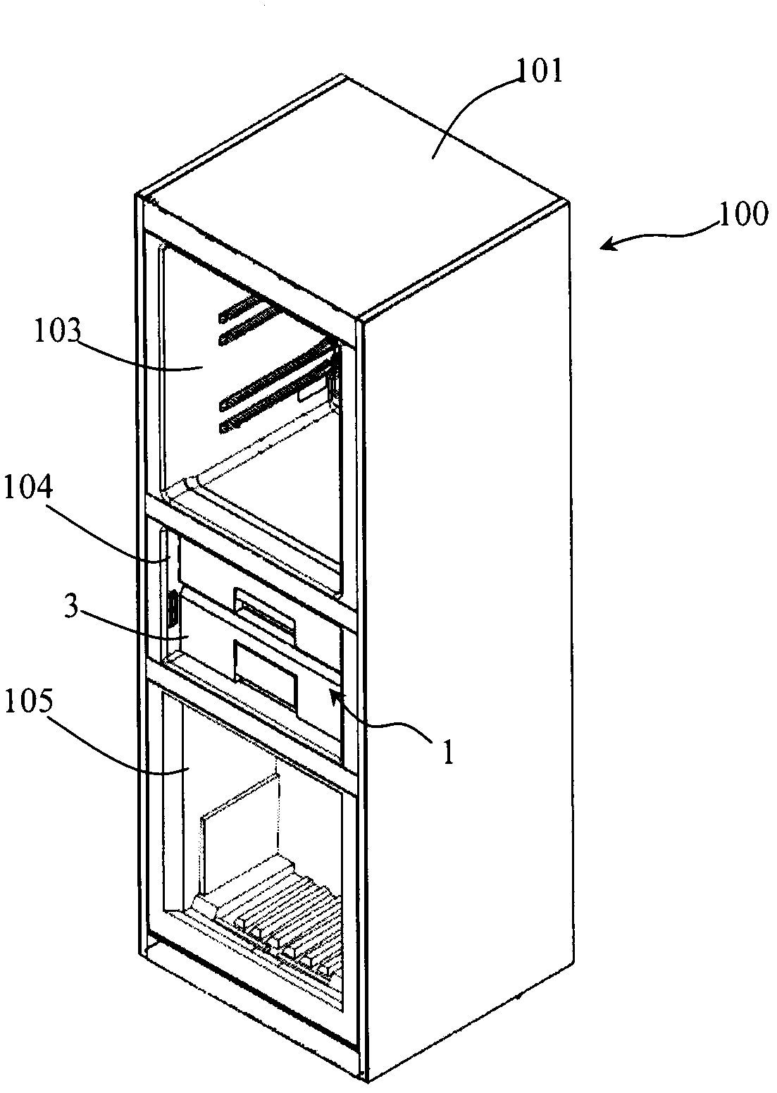
[0034] figure 1 A perspective view of a refrigeration appliance 100 according to a preferred embodiment of the present invention is shown, wherein the door is not shown. Such as figure 1 As shown, the refrigeration appliance 100 includes an insulated main body 101 having a plurality of storage compartments 103 , 104 , 105 . The storage compartments 103, 104, 105 can be selectively closed and opened by corresponding insulated doors (not shown) connected to the main body 101 .
[0035] The refrigeration appliance 100 includes a low-pressure storage unit 1 located in a storage room 104 . The refrigeration appliance 100 may include an evacuation device (such as a vacuum pump) in fluid communication with the storage space to evacuate the sealed storage space of the low-pressure storage unit 1 . In an alternative embodiment, it is also possible for the low-pressure storage unit 1 to be manually decompressed by the user (for example, by means of a suction tool independent of the r...
PUM
Abstract
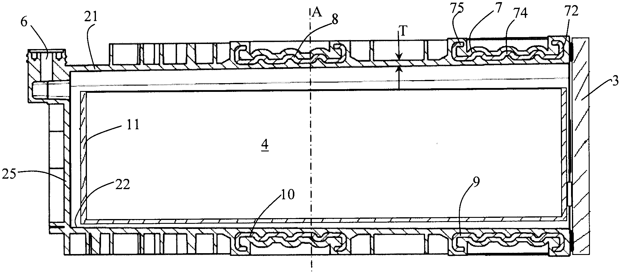
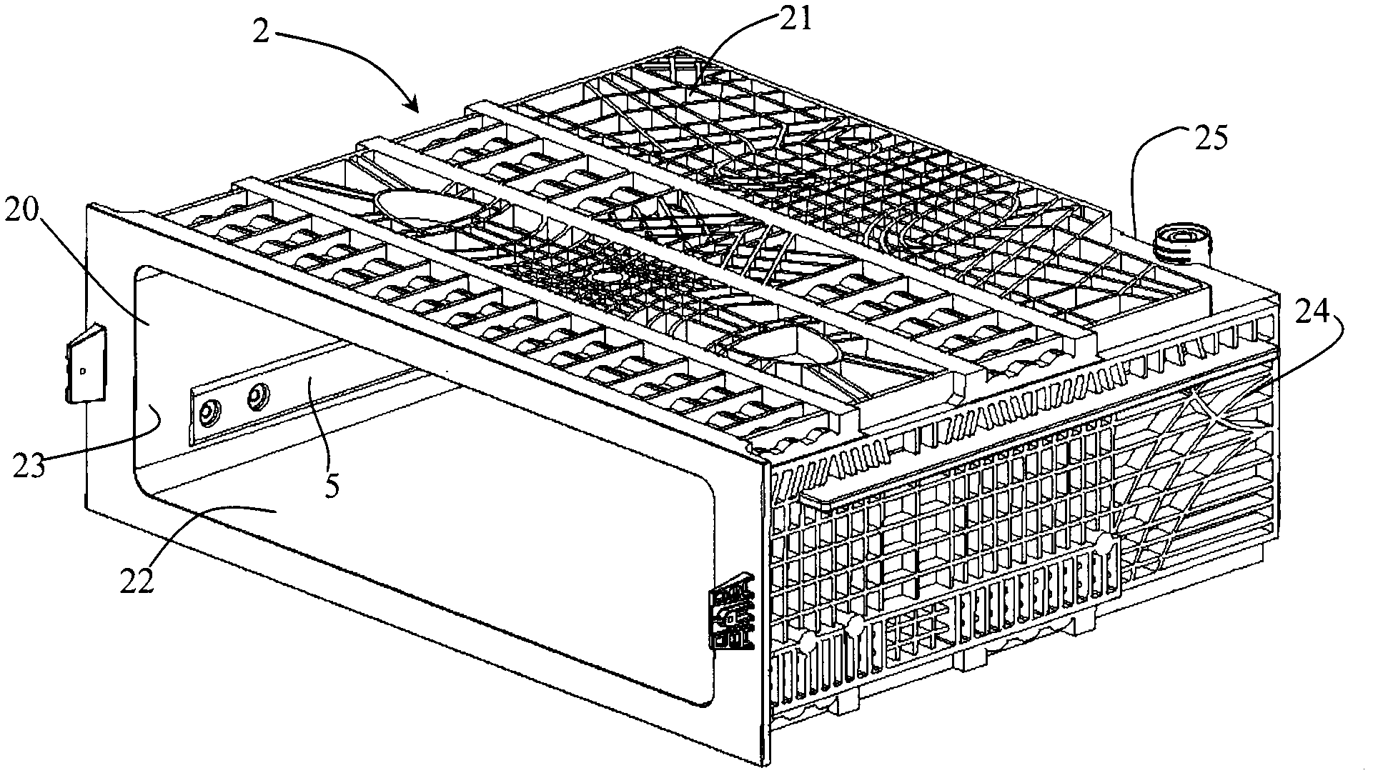
The invention discloses a storage unit for a refrigerating device. The storage unit comprises a plurality of walls (21, 22, 23, 24, 25, 3 and 21'), a vacuumizing storing space (4) defined by the walls (21, 22, 23, 24, 25, 3 and 21') and at least one of reinforcing parts (7, 8, 9, 7a, 7b and 7c) used for reinforcing one or more of the walls (21, 22, 23, 24, 25, 3 and 21'), wherein at least part of the reinforcing parts (7, 8, 9, 7a, 7b and 7c) are embedded into the one or more of the walls (21, 22, 23, 24, 25, 3 and 21').
Description
[technical field] [0001] The invention relates to a refrigeration appliance, in particular to a refrigeration appliance with a low-pressure storage unit such as a refrigerator. The invention also relates to a low-pressure storage unit for a refrigeration appliance. [Background technique] [0002] Refrigeration appliances that can store items in a low pressure environment are known in the prior art. Such refrigerating appliances usually have an evacuable storage chamber. By evacuating the gas in the storage chamber, the air content in the storage chamber is reduced to weaken the oxidation process of the food, thereby prolonging the preservation time and quality of the food. [0003] In the refrigerating appliance disclosed in Chinese patent application CN 1013243942A with an evacuable storage chamber (also called "low-pressure chamber" or "vacuum chamber"), the main body of the low-pressure chamber with the food access port includes a A box-shaped resin outer profile and a ...
Claims
Application Information
Patent Timeline
Application Date:The date an application was filed.
Publication Date:The date a patent or application was officially published.
First Publication Date:The earliest publication date of a patent with the same application number.
Issue Date:Publication date of the patent grant document.
PCT Entry Date:The Entry date of PCT National Phase.
Estimated Expiry Date:The statutory expiry date of a patent right according to the Patent Law, and it is the longest term of protection that the patent right can achieve without the termination of the patent right due to other reasons(Term extension factor has been taken into account ).
Invalid Date:Actual expiry date is based on effective date or publication date of legal transaction data of invalid patent.
