
Lightning impulse test system and method for electric equipment

A technology for power equipment and lightning strike, applied in the direction of testing circuits, testing dielectric strength, etc., can solve the problems of wave front time and oscillation overshoot not meeting the requirements, oscillation or overshoot, etc., to solve the wave front time and oscillation. Effect of Amplitude Influence

Active Publication Date: 2016-08-24
鑫大变压器有限公司
View PDF2 Cites 1 Cited by
  • Summary
  • Abstract
  • Description
  • Claims
  • Application Information

AI Technical Summary

Problems solved by technology

In this way, the wave front time T1 is greater than 1.56μs and / or the oscillation is greater than 10%. In order to obtain a smaller wave front time (preferably meeting the standard specified range), it is inevitable to generate oscillation or overshoot at the peak of the lightning impulse
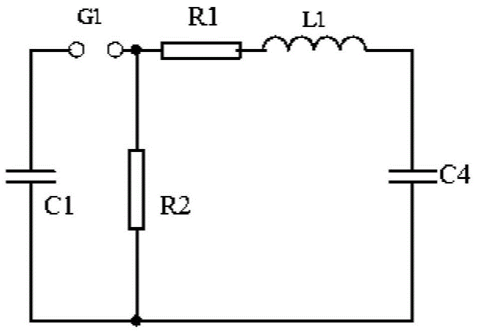
[0006] In the prior art, in order to ensure that the wave front time T1 meets the standard requirements, it is possible to reduce the wave front resistance R1, but the existence of the loop inductance L1 will cause oscillation overshoot at the peak of the shock waveform, and increasing the wave front resistance R1 will affect the oscillation overshoot It has a certain inhibitory effect. In this contradictory situation, it often occurs that the oscillation overshoot is greater than 10% in order to ensure the wave front time. Even for some products, the wave front time of the lightning shock and the oscillation overshoot even appear. Phenomena that do not meet the requirements
Although the method of connecting a capacitor in parallel to the wave front resistance R1 can improve this situation, it cannot fundamentally change the problem of the loop inductance L1

Method used


Image

  • Lightning impulse test system and method for electric equipment
  • Lightning impulse test system and method for electric equipment
  • Lightning impulse test system and method for electric equipment

Examples


Embodiment Construction

[0032] In order to make the above-mentioned purposes, features and advantages of the present invention more obvious and understandable, the specific implementation modes of the present invention will be described in detail below in conjunction with the accompanying drawings, so that the above-mentioned and other purposes, features and advantages of the present invention will be clearer. Like reference numerals designate like parts throughout the drawings. The drawings have not been drawn to scale, emphasis instead being placed upon illustrating the gist of the invention.

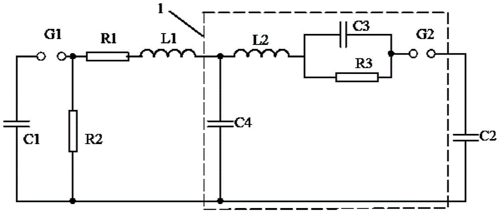
[0033] The power equipment in the present invention refers to equipment such as transformers, reactors and the like used in power systems with a relatively large inlet capacitance C2 and high voltage and large capacity.

[0034] The lightning impact test system and test method of electric equipment of the present invention are provided with a steepening loop, and its specific examples are as follows:

[003...


PUM


Abstract

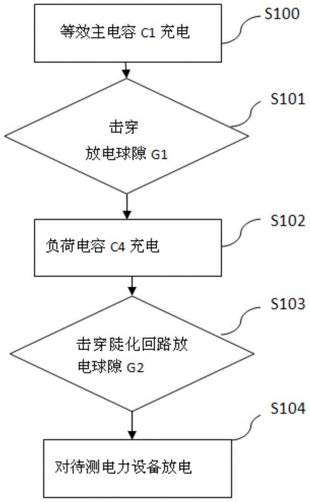
The invention provides a lightning impulse test system for electric equipment, which includes an impulse voltage generator, wherein a steepening circuit for secondary discharge is provided between the impulse voltage generator and the electric equipment to be tested. By setting the steepening circuit, the impulse voltage generator first charges the steepening circuit when discharging, and then conducts the lightning impulse test on the power equipment to be tested through the steepening circuit discharge. The secondary discharge technology is used, and the lead inductance of the steepening circuit is relatively high. It solves the problem that the impact of the large loop inductance in the impulse voltage generator on the wave front time and oscillation amplitude exceeds the standard.

Description

technical field [0001] The invention relates to the field of lightning impulse test of electric equipment, in particular to a lightning impulse test system and method of electric equipment. Background technique [0002] In the power system, it is generally necessary to transmit or exchange power through high voltage, which leads to the high voltage withstand function of the power equipment in the power system, and in the actual power system, most of the equipment is in the Relatively harsh environments, and due to weather and other influences, such as lightning, will also have a greater impact on electrical equipment. Therefore, there is a high requirement for lightning impact capability for electrical equipment. At the same time, how to test the lightning impact capability of electrical equipment is also very important. [0003] The equivalent circuit of the lightning impulse test system for existing power equipment is as follows: figure 1 , the impulse voltage generator...

Claims


Application Information

Patent Timeline
Patent Type & Authority Patents(China)
IPC IPC(8): G01R31/12G01R31/14
Inventor 陈道辉陈奎杜建嵩孙捷周敬伟
Owner 鑫大变压器有限公司
Learn More