
Wind Separator and Wind Wind Separation System

A winnowing machine and winnowing technology, applied in the direction of solid separation, separating solids from solids with airflow, chemical instruments and methods, etc., can solve the problem of high impurity content of light substances, mixing in heavy substances, light Issues such as easy reverse decline in quality

Active Publication Date: 2015-08-26
ZOOMLION ENVIRONMENTAL IND CO LTD
View PDF6 Cites 0 Cited by
  • Summary
  • Abstract
  • Description
  • Claims
  • Application Information

AI Technical Summary

Problems solved by technology

[0006] Although the sorting quality and air separation efficiency of the winnowing machine can be improved by setting the above-mentioned conveyor, in the above-mentioned winnowing machine, since the conveying surface of the conveying machine is a plane, that is, the conveying surface has the same inclination angle in the entire length direction, so there are disadvantages The above defects: when the inclination angle of the conveying surface is small, the textiles (relatively heavy materials) in the materials to be air-selected are easily attached to the conveying surface after being scattered and dropped in the air-selecting room, and a large friction force is obtained. As a result, it is transported up by the belt and mixed into the light materials, so that the light materials selected by wind have a higher impurity rate; because the light materials selected by wind will accumulate due to the large inclination angle during the migration process with the belt, when the conveying surface If the inclination angle is too large, it will cause the accumulated light objects to easily slide down to the heavy object discharge port in the reverse direction and be mixed into the heavy objects. In this case, the distance between the tail of the conveyor and the winnowing chamber Small, when encountering light objects such as cartons, it is easy to block the air duct, which will cause the entire sorting system to collapse

Method used


Image

  • Wind Separator and Wind Wind Separation System
  • Wind Separator and Wind Wind Separation System
  • Wind Separator and Wind Wind Separation System

Examples


Embodiment Construction

[0029] Specific embodiments of the present invention will be described in detail below in conjunction with the accompanying drawings. It should be understood that the specific embodiments described here are only used to illustrate and explain the present invention, and are not intended to limit the present invention.

[0030] In the present invention, in the case of no contrary description, the used orientation words such as "upper and lower" are defined under the normal use state of the winnowing machine of the present invention, and usually refer to the upper position shown in the accompanying drawings. , and below, "inside and outside" refer to inside and outside with respect to the outline of each component itself.

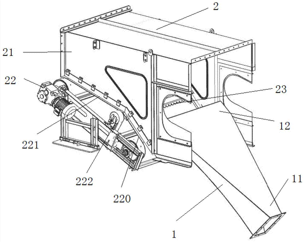
[0031] Such as figure 1 As shown, the winnowing machine provided by the present invention mainly includes a blower fan (not shown), an air distributor 1, a winnowing chamber 2, a feeder and a heavy object conveyor.

[0032] The air distributor 1 is a roughly...


PUM


Abstract

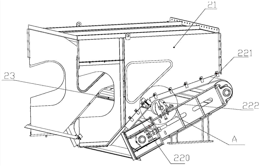
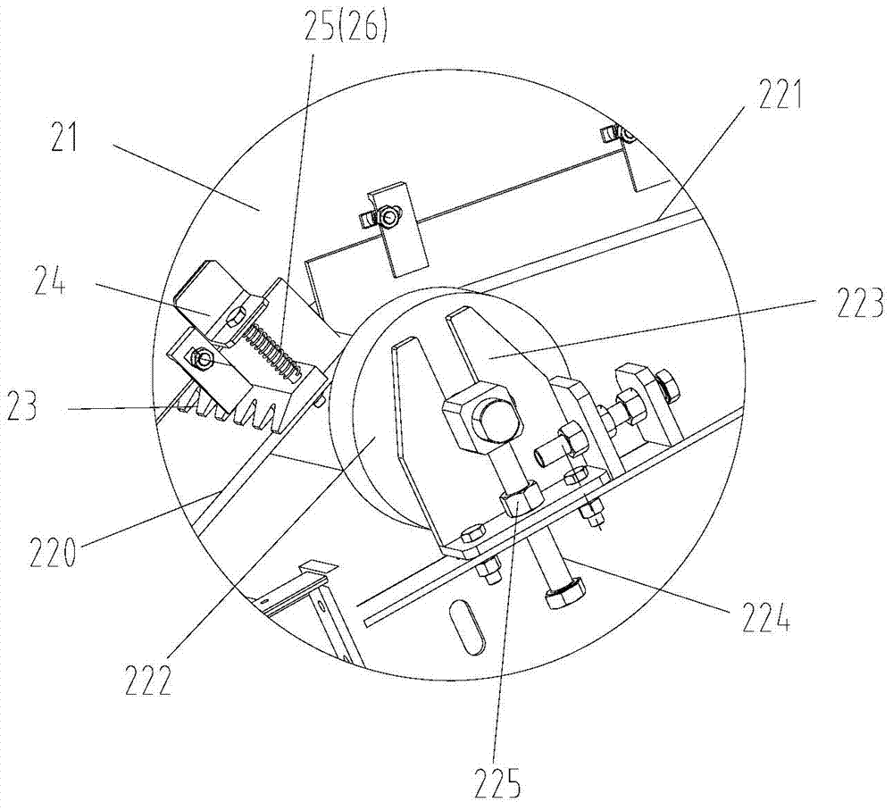
The invention discloses a winnowing machine which comprises a fan, an air distributor (1) and a winnowing chamber (2). The winnowing chamber (2) comprises a casing (21) and a belt conveyor (22) arranged in the casing, an inlet and an outlet are formed in the casing of the winnowing chamber, an air inlet is arranged at one end of the air distributor, an air nozzle (12) is formed in the other end of the air distributor, an outlet of the fan is connected with the air inlet of the air distributor, and the air nozzle of the air distributor extends out of the inlet of the winnowing chamber. The conveying face of the belt conveyor comprises a first portion (220) and a second portion (221) which are connected, wherein the first portion obliquely extends from the inlet of the winnowing chamber upward, the second portion extends from the first portion to the outlet of the winnowing chamber, and a dip angle of the first portion is larger than that of the second portion. The invention further discloses a wind power winnowing system including the winnowing machine. By adopting the scheme, the winnowing machine can well winnow heavy and light substances in materials.

Description

technical field [0001] The present invention relates to the field of wind separation of mixed materials, such as the field of chemical industry and the field of municipal solid waste separation (such as the field of plastic separation), in particular, it relates to a wind separation machine, and also relates to a wind separation system. Background technique [0002] With the improvement of living standards of urban residents, the content of plastics in domestic waste continues to increase. Plastic has increasingly become the focus of waste recycling and recycling. Plastic mechanical sorting technology has generally adopted wind sorting technology, that is, the sorting of plastic waste in domestic waste is realized through the wind sorting system. Of course, the wind separation system can also be applied to other fields, such as the chemical industry. [0003] Air separation systems usually include air separators and separators. [0004] The utility model patent with the p...

Claims


Application Information

Patent Timeline
Patent Type & Authority Patents(China)
IPC IPC(8): B07B4/00B07B11/06
Inventor 高根树
Owner ZOOMLION ENVIRONMENTAL IND CO LTD
Learn More