
Automatic cleaning machine for steel dies

An automatic cleaning and cleaning machine technology, which is applied in cleaning methods and tools, cleaning methods using tools, chemical instruments and methods, etc., can solve the problems of unreliable cleaning, unclean cleaning, and inaccurate alignment of steel mold joints and other problems, to achieve the effect of simple structure, easy promotion, and remarkable cleaning effect

Inactive Publication Date: 2014-02-05
SHANGHAI ZHONGJI PILE IND
View PDF8 Cites 7 Cited by
  • Summary
  • Abstract
  • Description
  • Claims
  • Application Information

AI Technical Summary

Problems solved by technology

[0002] In the production of concrete prestressed piles, the residual slurry in the steel mold seam brings many difficulties to the cleaning work in the manufacturing process: first, the steel mold is on the transfer and transportation equipment, and the manual cleaning is labor-intensive, and the cleaning is not clean; Second, the steel mold clamping mouth cannot be accurately aligned, resulting in deformation of the steel mold, affecting the quality of the pile, etc., and increasing the manufacturing cost of the product; third, cleaning the steel mold seam (mold edge) during the manual cleaning process There is no reliable method to control, which directly affects the overall quality of the product
[0003] In addition, the cleaning surface of the existing steel mold is not necessarily flat, it may be a large-angle inclined structure, and the existing cleaning machine can only remove the residual slurry on the horizontal surface of the steel mold, which is very difficult for the residual slurry on the steel mold slope. Difficult to clean, it requires secondary cleaning, which not only wastes time, but also wastes resources; there is an urgent need for a steel mold cleaning machine that can be used to clean the residual slurry on the surface of steel molds with different shapes

Method used


Image

  • Automatic cleaning machine for steel dies
  • Automatic cleaning machine for steel dies

Examples


Embodiment Construction

[0022] In order to make the technical means, creative features, goals and effects achieved by the present invention easy to understand, the present invention will be further described below in conjunction with specific illustrations.

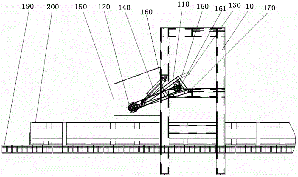
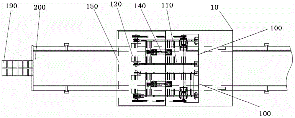
[0023] see figure 1 and figure 2 As shown, the present invention discloses a steel mold automatic cleaning machine, including a cleaning machine frame 10 and a PLC control system (not shown in the figure) for controlling the operation of the cleaning machine; the steel mold automatic cleaning machine also includes two symmetrically installed The cleaning device 100 on the cleaning machine frame has the same structure as the two cleaning devices, and both of them work independently during work without affecting each other.

[0024] The two cleaning devices 100 of the present invention all comprise lifting frame 110, wire brush 120, counterweight 130, cylinder 140, dust collection cover 150, drive motor 160 and belt 170; On the cleaning machine...


PUM


Abstract

The invention discloses an automatic cleaning machine for steel dies. The automatic cleaning machine comprises a cleaning machine frame, a PLC (Programmable Logic Controller) control system and two cleaning devices, wherein the PLC control system is used for controlling the cleaning machine to operate; the two cleaning devices are symmetrically installed on the cleaning machine frame; each cleaning device comprises a lifting frame, a steel wire brush, a balance weight, a cylinder, a dust collecting cover, a driving motor and a belt, wherein the lifting frame can be rotatably installed on the cleaning machine frame, the steel wire brush is installed on the front end of the lifting frame, the balance weight is installed on the back end of the lifting frame, the cylinder, the dust collecting cover and the driving motor are installed on the lifting frame, and the belt is used for driving the steel wire brush to operate. The automatic cleaning machine has the advantages of simple structure, convenience in use, high operating efficiency and high degree of automation, and the whole operation of the machine is controlled by the PLC system; additionally, the two cleaning devices which are independently operated are adopted, and the automatic cleaning machine has good cleaning effects on the steel dies at large inclined angles and the steel dies which move up and down during operation.

Description

technical field [0001] The invention relates to an automatic cleaning machine, in particular to an automatic steel mold cleaning machine. Background technique [0002] In the production of concrete prestressed piles, the residual slurry in the steel mold seam brings many difficulties to the cleaning work in the manufacturing process: first, the steel mold is on the transfer and transportation equipment, and the manual cleaning is labor-intensive, and the cleaning is not clean; Second, the steel mold clamping mouth cannot be accurately aligned, resulting in deformation of the steel mold, affecting the quality of the pile, etc., and increasing the manufacturing cost of the product; third, cleaning the steel mold seam (mold edge) during the manual cleaning process There is no reliable method to control, which directly affects the overall quality of the product. [0003] In addition, the cleaning surface of the existing steel mold is not necessarily flat, it may be a large-angl...

Claims


Application Information

Patent Timeline
Patent Type & Authority Applications(China)
IPC IPC(8): B08B1/04
CPCB08B1/30B08B1/12
Inventor 朱双彪孙亚卓
Owner SHANGHAI ZHONGJI PILE IND
Learn More