Drill working state automatic identification method suitable for hydraulic drill

An automatic identification and hydraulic drilling rig technology, which is applied in the field of mud logging, oil and gas exploration and development drilling, can solve problems such as inaccurate state judgment, and achieve the effect of automatic identification and easy realization

Active Publication Date: 2014-02-05
SHANGHAI GASOLINEEUM & CHEM EQUIP +2
View PDF11 Cites 2 Cited by
  • Summary
  • Abstract
  • Description
  • Claims
  • Application Information

AI Technical Summary

Problems solved by technology

[0007] The invention provides an automatic identification method for the working state of the hydraulic drilling rig, which is suitable for both conventional drilling rigs and hydraulic drilling rigs, can accurately identify the working state of the hydraulic drilling rig, and can solve the problem of heavy and light hook loads in conventional methods. The problem of inaccurate status judgment when the difference is not large

Method used


Image

  • Drill working state automatic identification method suitable for hydraulic drill

Examples


Embodiment Construction

[0037] Preferred embodiments of the present invention will be specifically described below.

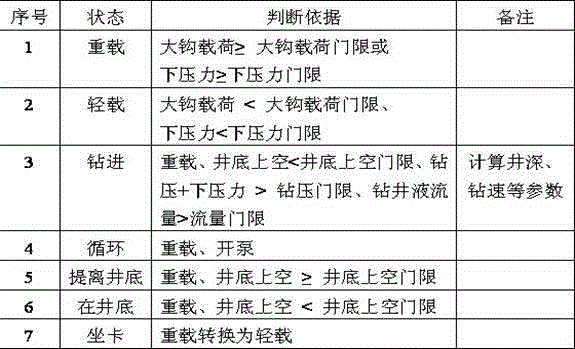
[0038] The present invention provides a drilling rig working state automatic identification method suitable for hydraulic drilling rigs, the automatic identification method includes the following steps:

[0039] Step 1. Install the suspension load sensor for measuring the load of the hook, the winch sensor for measuring the displacement of the hook, and the pumping sensor for measuring the flow rate of the drilling fluid on the corresponding position of the hydraulic drilling rig according to the conventional method;

[0040] Step 2. Connect a three-way joint in series to the pressure sensor for measuring the down pressure in the connection oil circuit of the down pressure gauge of the hydraulic drilling rig;

[0041] Step 3. The conventional signal receiving and processing module receives the hook load value measured by the suspension weight sensor, the hook displacement value measur...


PUM


Abstract

The invention discloses a drill working state automatic identification method suitable for a hydraulic drill. The method comprises the following steps: receiving a hook load value measured by a weight sensor, a hook displacement value measured by a winch sensor, a drilling liquid flow value measured by a pump stroke sensor and a lower pressure value measured by a pressure sensor; setting a hook load threshold value, a lower pressure threshold value, a shaft bottom overhead threshold value, a drilling fluid flow threshold value and a drilling pressure threshold value; automatically identifying the drill state according to a judging basis. The drill working state automatic identification method is suitable for the conventional drill as well as the hydraulic drill, the working state of the hydraulic drill can be identified accurately, and the problem of inaccurate of state judgment under the condition of small difference between heavy hook loads and light hook loads existing in the conventional method can be solved.

Description

technical field [0001] The invention relates to a method for automatically identifying the working state of a hydraulic drilling rig, which belongs to the technical field of drilling and mud logging in oil and gas exploration and development. Background technique [0002] During the drilling process in the field of oil and gas exploration and development, engineers and technicians need to timely and accurately measure the drilled well depth, master the drilling layers, and understand the working status of the drilling rig. At present, it is mainly done by on-site automatic measuring instruments. Well instrument, drilling parameter instrument, etc. The identification method of the drilling working state of these measuring equipment is to measure the displacement of the hook of the drilling rig by the winch sensor, the hook load of the drilling rig by the suspension weight sensor, and the pump impulse speed by the pump stroke sensor to comprehensively calculate and judge the d...

Claims


Application Information

Patent Timeline
Patent Type & Authority Applications(China)
IPC IPC(8): E21B47/00E21B45/00E21B47/04E21B47/06E21B21/08
Inventor 赵要强韩信礼李荣
Owner SHANGHAI GASOLINEEUM & CHEM EQUIP
Why Eureka
Try Eureka