Current detection circuit and device

A current detection circuit and current technology, applied in the direction of measuring current/voltage, components of electrical measuring instruments, measuring electricity, etc., can solve problems such as inability to distinguish/identify different working states or fault states

Pending Publication Date: 2021-12-14
SHENZHEN SILVER STAR INTELLIGENT TECH CO LTD
View PDF0 Cites 0 Cited by
  • Summary
  • Abstract
  • Description
  • Claims
  • Application Information

AI Technical Summary

Problems solved by technology

[0005] In view of this, the embodiment of the present application provides a current detection circuit and equipment, aiming to solve the problem that traditional PTC-based current detection cannot distinguish / identify different working states or fault states

Method used


Image

  • Current detection circuit and device
  • Current detection circuit and device
  • Current detection circuit and device

Examples


Embodiment Construction

[0027] In order to make the purpose, technical solution and advantages of the present application clearer, the present application will be further described in detail below in conjunction with the accompanying drawings and embodiments. It should be understood that the specific embodiments described here are only used to explain the present application, and are not intended to limit the present application.

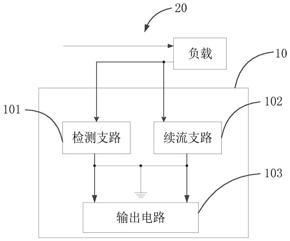
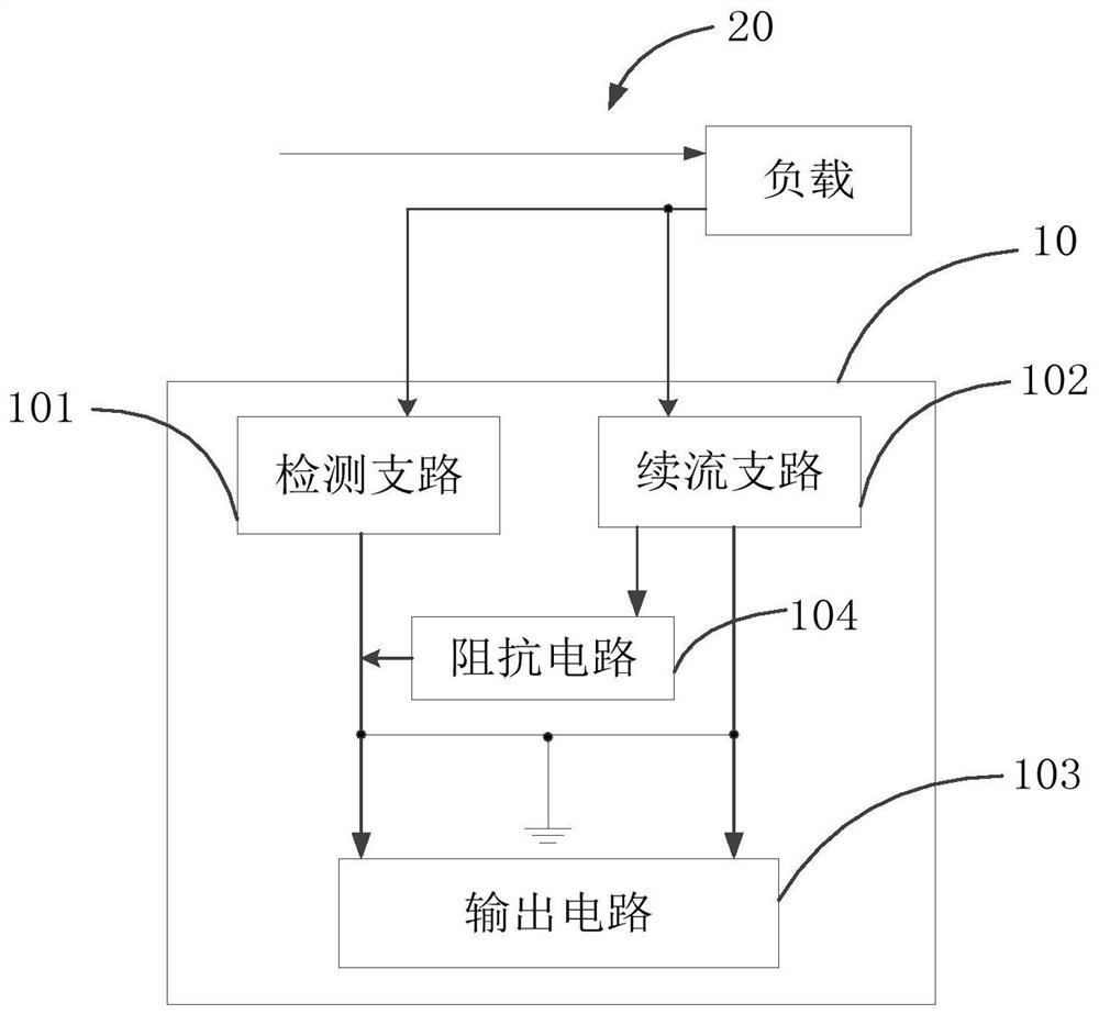
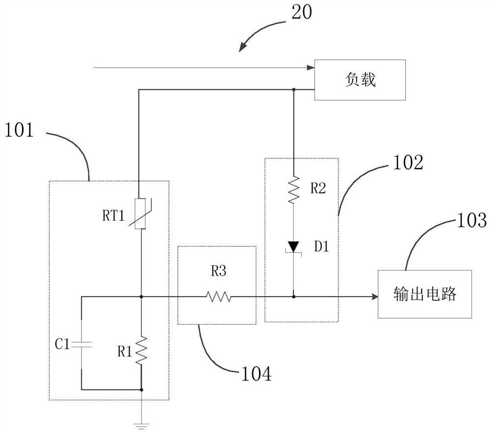
[0028] The current detection circuit and equipment in the embodiment of the present application introduces a freewheeling branch on the basis of the traditional detection branch, which can at least provide a function between the normal working current, the typical overcurrent current and the working current after the PTC overcurrent triggers. The clearly differentiated detection signals enable the user or the system to accurately identify the working status and fault status on the current transmission circuit.

[0029] As an example and not limitation, the device may be at...


PUM


Abstract

A current detection circuit and device are provided. The current detection circuit is connected with a current transmission loop, and the current detection circuit comprises a detection branch which comprises a thermosensitive device and is used for collecting the working current of the current transmission loop and outputting a first detection voltage; a follow current branch used for being switched on when the working current is greater than or equal to a thermosensitive trigger value so as to output a second detection voltage greater than a thermosensitive voltage value; an output circuit which is connected with the detection branch and the follow current branch, and is used for outputting a first output signal for indicating a first working state when the first detection voltage is received and the first detection voltage is smaller than an overcurrent threshold value, outputting a second working state when the first detection voltage is larger than or equal to the overcurrent threshold value, and when the second detection voltage is received, outputting and indicating a third working state, so that a user or a system can accurately identify a working state and a fault state on a current transmission loop, and the functions of equipment are more perfect.

Description

technical field [0001] The application belongs to the field of electronic circuits, and in particular relates to a current detection circuit and equipment. Background technique [0002] Generally, the positive temperature coefficient thermal material (Positive Temperature Coefficient, PTC) is used for overcurrent protection. When the load current exceeds the trigger current of the PTC (such as overcurrent or short circuit), the resistance of the PTC rises rapidly, that is, the output resistance of the load circuit Larger, the output performance will be weakened sharply, and the purpose of cutting off the load and protecting the load and driving circuit will be achieved in disguise. [0003] At present, some drive circuits have a current sampling module. When the PTC is triggered, the loop current becomes smaller. This current is not 0, but is determined by the heat generation. Generally, a certain current still flows through the loop. At this time, it is difficult for the s...

Claims


Application Information

Patent Timeline
Patent Type & Authority Applications(China)
IPC IPC(8): G01R19/165G01R1/30
CPCG01R19/16571G01R1/30
Inventor 李铭男赵泽鹏徐自成房炬康
Owner SHENZHEN SILVER STAR INTELLIGENT TECH CO LTD
Why Eureka
Try Eureka