
Auxiliary umbrella installing method and auxiliary umbrella

An installation method and umbrella skirt technology are applied to the installation method of auxiliary umbrellas and the field of auxiliary umbrellas, which can solve the problems of limited service life, inability to fundamentally guarantee long-term operation, and high cost, and achieve the effect of long service life.

Active Publication Date: 2014-02-05
JIANGSU SHENMA ELECTRIC CO LTD
View PDF10 Cites 4 Cited by
  • Summary
  • Abstract
  • Description
  • Claims
  • Application Information

AI Technical Summary

Problems solved by technology

However, for power stations that have been built and are in operation, one method is to spray RTV / PRTV coatings on the surface of porcelain insulators. This method is not only costly, but also has a limited life, and cannot fundamentally guarantee long-term operation.

Method used


Image

  • Auxiliary umbrella installing method and auxiliary umbrella
  • Auxiliary umbrella installing method and auxiliary umbrella
  • Auxiliary umbrella installing method and auxiliary umbrella

Examples


Embodiment 1

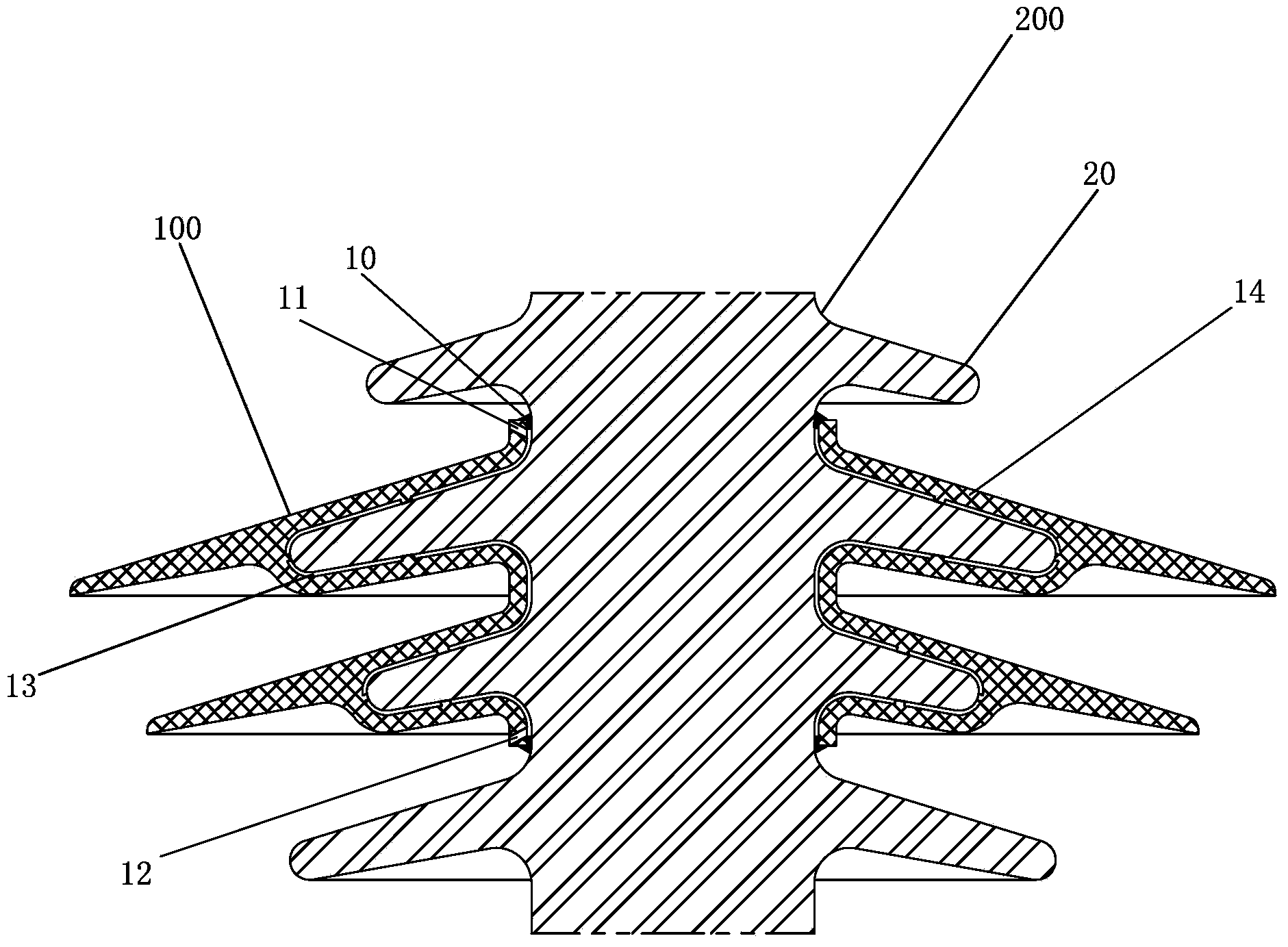
[0020] Such as figure 1 As shown, it is a schematic diagram of the auxiliary umbrella 100 sleeved on the insulator 200 in this embodiment. The insulator 200 includes several sheds 20 . The auxiliary umbrella 100 includes a fixed portion 14 covering the upper surface of the shed 20 , the upper end of the fixed portion 14 is provided with an air vent 11 , and the lower end of the auxiliary umbrella 100 is provided with a glue injection hole 12 . Blocking objects 10 are provided at positions where the upper and lower ends of the auxiliary umbrella 100 are in contact with the insulator 200 . A space 13 is provided on the surface of the auxiliary umbrella 100 and the umbrella skirt 20 for subsequent filling of glue.

[0021] The installation method of the auxiliary umbrella of the present embodiment comprises the following steps:

[0022] a. Set the auxiliary umbrella 100 on the umbrella skirt 20;

[0023] b. The upper and lower ends of the auxiliary umbrella 100 connected with...

Embodiment 2

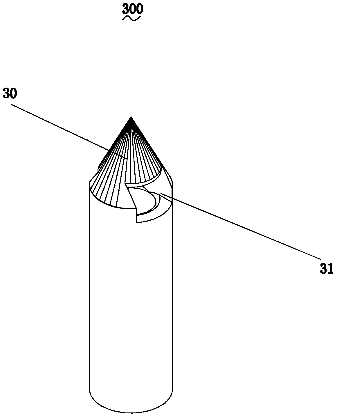
[0028] Such as figure 2 Shown is a schematic diagram of the needle 300 used in the second embodiment of the present invention. A tip 30 is provided on the needle 300 for piercing the auxiliary umbrella, and the other end of the needle 300 is connected with a glue injection tube. A glue outlet 31 is provided on the side of the tip 30, and the glue outlet 31 is arranged on the side to facilitate the smooth flow of the glue from the needle 300 without being blocked. The lower part of the auxiliary umbrella of the present embodiment does not need to reserve a glue injection hole.

[0029] The installation method of the auxiliary umbrella of the present embodiment comprises the following steps:

[0030] a. Set the auxiliary umbrella cover on the umbrella skirt;

[0031] b. Seal the upper and lower ends of the auxiliary umbrella and the insulator with plugging materials, seal the opening of the auxiliary umbrella, and reserve the vent hole on the upper part of the auxiliary umbr...


PUM


Abstract

The invention discloses an auxiliary umbrella installing method and an auxiliary umbrella. The auxiliary umbrella installing method comprises the following steps: step a, the auxiliary umbrella is arranged on umbrella skirts where the auxiliary umbrella needs to be arranged in a sleeved mode; step b, the upper end and lower end, connected with an insulator, of the auxiliary umbrella are blocked, so that a relatively closed space is formed between the auxiliary umbrella and the insulator, and the space is communicated with the outside through vent holes; step c, a glue solution is injected in the space till air in the space is completely discharged from the vent holes, and the space is filled with the glue solution. Beside, the invention further discloses the auxiliary umbrella which is mounted on the insulator, wherein the insulator comprises the multiple umbrella skirts, the auxiliary umbrella comprises fixing parts which cover the upper surfaces of the umbrella skirts, and the fixing parts are connected to the umbrella skirts through binders and provided with the vent holes. According to the auxiliary umbrella installing method and the auxiliary umbrella, the auxiliary umbrella can be firmly fixed to the insulator, so that the service life of the auxiliary umbrella is quite long.

Description

technical field [0001] The invention relates to the field of electric equipment manufacturing, in particular to a method for installing an auxiliary umbrella and an auxiliary umbrella. Background technique [0002] Since high-voltage power transmission was enabled, porcelain materials were usually used as external insulation materials in the early days. With the deterioration of the atmospheric environment, the air pollution level is getting higher and higher, and the pollution flashover accidents of porcelain insulators continue to occur under the condition of pollution accumulation, causing huge losses to the power grid and seriously affecting the smooth operation of the power grid. At the same time, due to problems such as heavy rain and icing, accidents such as rain flash and ice flash of porcelain insulators tend to occur frequently. [0003] At present, in view of the pollution flashover problem, the power grid company recommends the use of composite insulators in new...

Claims


Application Information

Patent Timeline
IPC IPC(8): H01B17/66
Inventor 马斌方江周曙琛宋波孙作敬姜建泉
Owner JIANGSU SHENMA ELECTRIC CO LTD
Learn More