
Capacitor bank switching vacuum circuit breaker

A technology of vacuum circuit breaker and capacitor bank, applied in the direction of high-voltage air circuit breaker, circuit, electric switch, etc., can solve the problem of high re-ignition probability of switching capacitor bank, and achieve the effect of good insulation reliability

Inactive Publication Date: 2014-02-05
SHANDONG TAIKAI VACUUM SWITCH
View PDF7 Cites 2 Cited by
  • Summary
  • Abstract
  • Description
  • Claims
  • Application Information

AI Technical Summary

Problems solved by technology

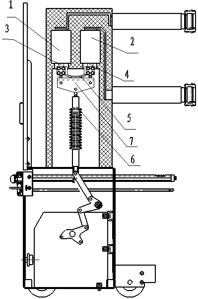
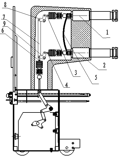
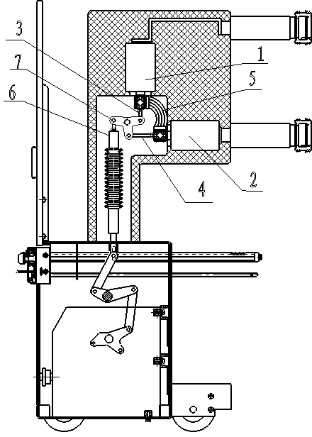
[0003] In order to solve the problem of high reignition probability of switching capacitor banks in existing circuit breakers, the present invention provides a capacitor bank switching vacuum circuit breaker using series breaking technology. The technical solution adopted is:

Method used


Image

  • Capacitor bank switching vacuum circuit breaker
  • Capacitor bank switching vacuum circuit breaker
  • Capacitor bank switching vacuum circuit breaker

Examples


Embodiment Construction

[0011] The present invention will be further described below in conjunction with the accompanying drawings.

[0012] The present invention adopts the frame bearing mode, the spring mechanism is on the bottom, the transmission mechanism is in the middle, and the primary conductive parts are on the upper, middle and lower arrangement mode. Each phase is formed by two 24kV arc extinguishing chambers, and the two static ends of the arc extinguishing chamber are respectively made of The conductive parts are led to the upper and lower outlet sockets as the upper and lower poles of the circuit breaker. The conductive part cooperates with the spring mechanism through the bearing of the frame to meet the opening and closing function of the circuit breaker.

[0013] like figure 1 As shown, the arc extinguishing chamber Ⅰ1 and arc extinguishing chamber Ⅱ2 of each phase in the conductive parts are vertically arranged left and right. Connect 5 phases short. The circuit breaker also inclu...


PUM


Abstract

The invention discloses a capacitor bank switching vacuum circuit breaker. The capacitor bank switching vacuum circuit breaker is sequentially provided with a conductive part, a transmission mechanism and a spring mechanism from top to bottom. An arc extinguish chamber I and an arc extinguish chamber II of each phase in the conductive part are vertically arranged left and right, a movable conductive rod I at the bottom of the arc extinguish chamber I is in short-circuited connection with a movable conductive rod II at the bottom of the arc extinguish chamber II in a flexible mode, the top end of an isolating pull rod in the transmission mechanism is connected with a connecting plate, and the connecting plate is connected with the movable conductive rod I and the movable conductive rod II. A serial connection fracture mode is adopted on a vacuum fracture, and the problem that the reignition probability is high when a common vacuum circuit breaker is used for switching a capacitor bank is solved.

Description

technical field [0001] The invention relates to a vacuum circuit breaker. Background technique [0002] The role of the reactive power compensation device in the power supply system is to improve the power factor of the power grid, reduce the loss of power supply transformers and transmission lines, improve power supply efficiency, and improve the power supply environment. The most economical and effective way to improve the power factor is to install parallel capacitor banks. However, at present, the probability of reignition of vacuum circuit breakers when switching capacitor banks is still high. According to the data of Shaoxing Test Station, in the 10kV field, domestic vacuum switches have The restrike rate of the switching capacitor bank has been around 1%. For the 35kV vacuum circuit breaker switching capacitor bank, the restrike probability is more than 2%, and some products even reach nearly 10% restrike probability. Contents of the invention [0003] In order to...

Claims


Application Information

Patent Timeline
IPC IPC(8): H01H33/66H01H33/664
Inventor 秦成伟霍家鹏王珂林卫东刘炳辉
Owner SHANDONG TAIKAI VACUUM SWITCH
Learn More