
An internal locking module of a circuit breaker

A circuit breaker and locking end technology, applied in the low-voltage electrical field, can solve problems such as poor reliability, and achieve the effects of convenient operation, strong reliability and convenient control

Active Publication Date: 2016-04-13
DELIXI ELECTRIC
View PDF7 Cites 0 Cited by
  • Summary
  • Abstract
  • Description
  • Claims
  • Application Information

AI Technical Summary

Problems solved by technology

[0005] In order to solve the problem that the handle of the circuit breaker in the prior art is locked by an external locking device and the reliability is relatively poor, an internal locking module of the circuit breaker with good reliability and easy operation is provided

Method used


Image

  • An internal locking module of a circuit breaker
  • An internal locking module of a circuit breaker
  • An internal locking module of a circuit breaker

Examples


Embodiment 1

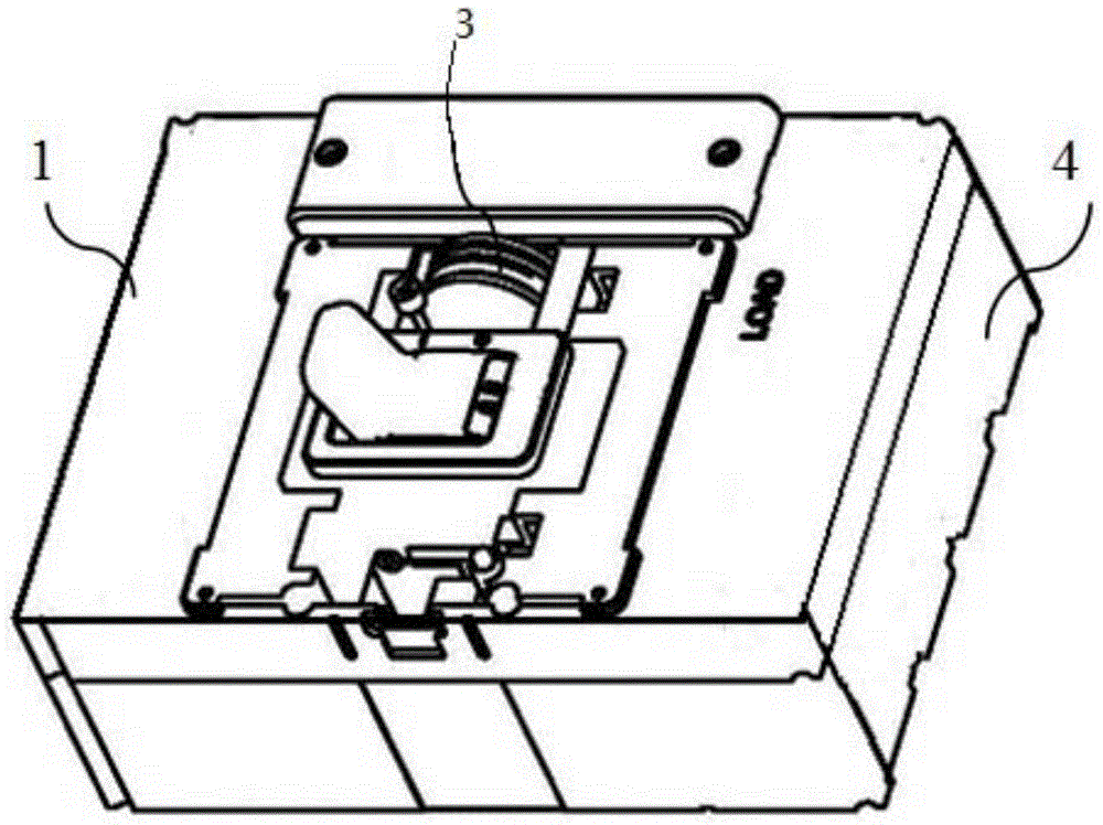
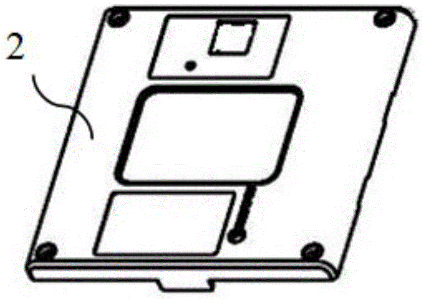
[0041] Such as figure 1 Shown is a preferred embodiment of the internal locking module of a circuit breaker of the present invention. The internal locking module is set in the accessory box 7 of the circuit breaker 4, and the accessory box 7 is set on the middle cover 1. After the locking module is assembled, the upper cover 2 can be used, such as figure 2 shown.

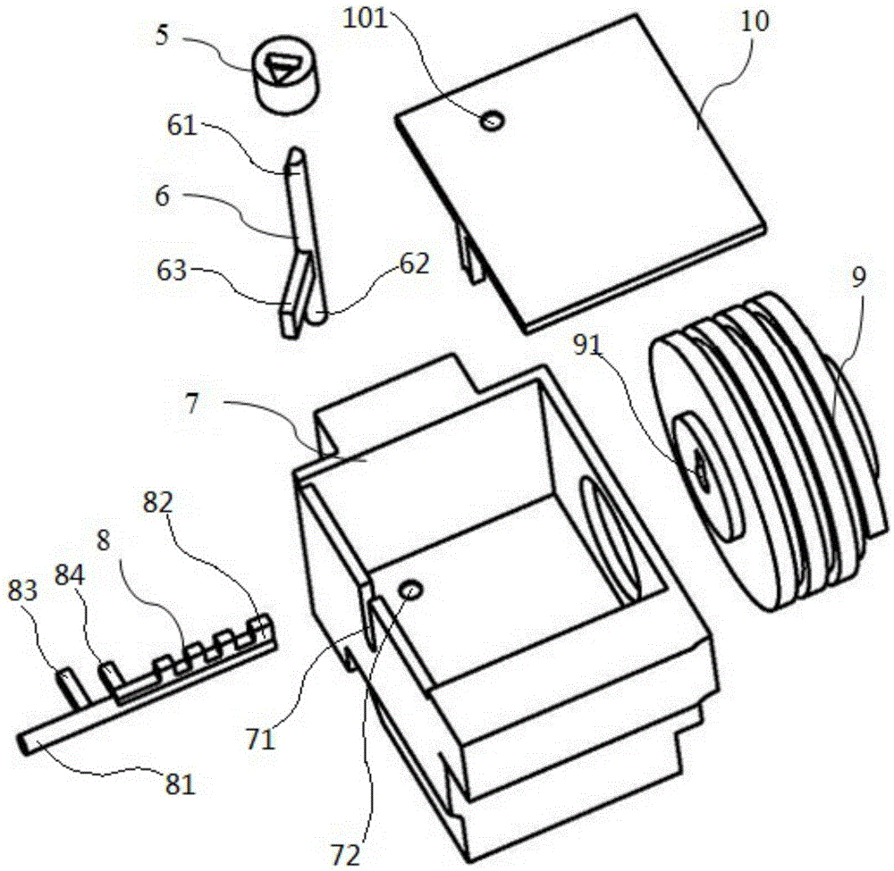
[0042] Such as image 3 As shown, the locking module 3 includes a lock cylinder 8, a lock cylinder limiting mechanism and a lock cylinder driving mechanism.

[0043] The lock core 8, or called a latch, has one end of the lock core 8 as a locking end 81 and the other end as a mounting end 82, and a suitable surface is formed on the side wall of the accessory box 7 close to the handle 19 of the circuit breaker. The lock cylinder hole 71 protruding from the locking end 81, the locking end 81 protruding from the lock cylinder hole 71 is suitable for cooperating with the handle 19 to lock the handle 19, specifically,...

Embodiment 2

[0051] The difference between this embodiment and Embodiment 1 is that the length of the locking end 81 of the lock cylinder 8 in this embodiment is suitable for sequentially locking the lever 11 of the handle 19, the bracket 12 of the circuit breaker 4 and the jumper. 13. To play the role of locking circuit breaker tripping protection, suitable for marine circuit breakers to prevent unnecessary tripping due to circuit breaker vibration. The lock cylinder limiting mechanism includes a side wall opposite to the lock cylinder hole 71 , a first baffle plate 83 and a second baffle plate 84 .

[0052] Such as Figure 7 As shown, the side wall of the lock cylinder hole 71 is provided with an assembly hole for inserting the installation end 81 of the lock cylinder 8 to support the installation end 81 .

[0053] The first baffle plate 83 and the second baffle plate 84 are arranged on the lock core 8 , and the first baffle plate 83 and the second baffle plate 84 protrude from the cyli...


PUM


Abstract

The invention discloses an interior locking module of a circuit breaker. The interior locking module is arranged in an accessory box of the circuit breaker and comprises a lock core, a lock core limiting mechanism and a lock core driving mechanism. One end of the lock core is a locking end, and the other end of the lock core is an installing end. A lock core hole which the locking end can stretch out of is formed in the lateral wall, close to a handle of the circuit breaker, of the accessory box, the locking end stretches out of the lock core hole to be suitable for being matched with the handle for locking the handle, and the installing end is arranged in the accessory box in a supported mode. The lock core limiting mechanism is used for supporting the installing end of the lock core and limiting the locking end to the position where the handle is locked or the position where the locking end completely contracts into the lock core hole. The lock core driving mechanism is used for driving the lock core to move to make the locking end stretch out of the lock core hole or contract into the lock core hole. The interior locking module is easy and convenient to operate and can reliably lock the circuit breaker and avoid misoperation.

Description

technical field [0001] The invention relates to the field of low-voltage electrical technology, in particular to an internal locking module of a circuit breaker. Background technique [0002] The existing circuit breakers for power distribution and earth leakage circuit breakers are manually controlled to close and open the circuit breakers through operating handles. When the circuit breaker is installed in the power distribution cabinet or power distribution room, in order to prevent maintenance personnel or outsiders from accidentally touching the handle and causing misoperation, a locking auxiliary device will be added to the handle and a padlock will be used to lock the handle of the circuit breaker. closed position or open position. [0003] For example, Chinese patent document CN101645377 discloses a handle lock device of a circuit breaker and a circuit breaker, wherein the handle for operating a rocker switch protrudes outward from the box cover of the circuit breake...

Claims


Application Information

Patent Timeline
Patent Type & Authority Patents(China)
IPC IPC(8): H01H71/00H01H9/28
Inventor 倪加岚何海良刘云飞宋志文
Owner DELIXI ELECTRIC
Learn More