Combustion chamber construction for opposed-piston engines

A technology of combustion chamber and internal combustion engine, which is applied in the field of combustion chamber and can solve the problems of reducing the speed of engine thermal efficiency

Active Publication Date: 2014-02-05
ACHATES POWERS INC
View PDF5 Cites 10 Cited by
  • Summary
  • Abstract
  • Description
  • Claims
  • Application Information

AI Technical Summary

Problems solved by technology

A higher velocity vector of the vortex occurs near the cylinder wall, which provides the worst case for heat loss: the hot gas has a velocity that transfers heat to the cylinder wall and reduces the thermal efficiency of the engine

Method used


Image

  • Combustion chamber construction for opposed-piston engines
  • Combustion chamber construction for opposed-piston engines
  • Combustion chamber construction for opposed-piston engines

Examples


Embodiment Construction

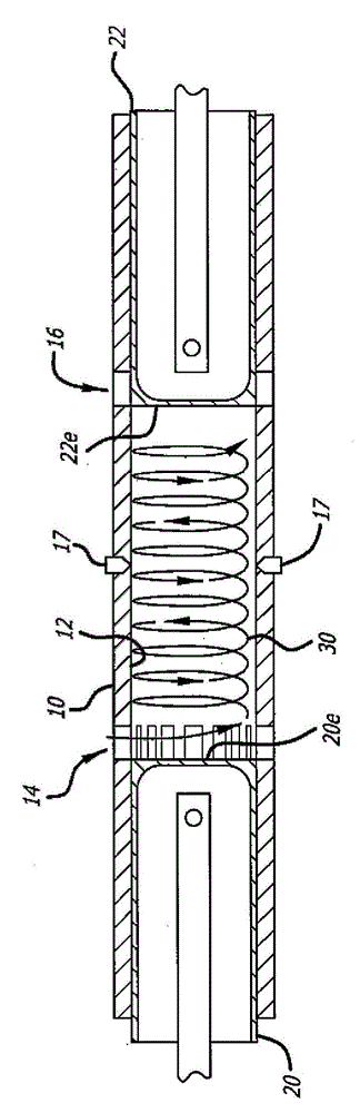
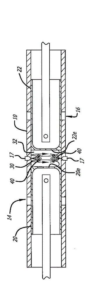
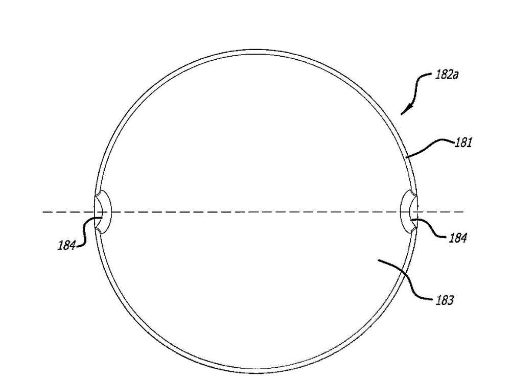
[0027] In a configuration to be described, an internal combustion engine includes at least one cylinder having longitudinally separated exhaust and intake ports formed or machined in the side walls of the cylinder. A pair of pistons are disposed oppositely within the bore of the cylinder, and a combustion chamber is defined between opposing end surfaces of the pistons as they move toward respective top dead center positions. A circumferential region defines a periphery on each of the end surfaces. The combustion chamber structure comprises a cavity or space within the bore (defined by opposed end surfaces of the piston) having, at least in plan, an elongated groove-like shape with an elliptical appearance. The elongated combustion chamber shape extends radially of the cylinder and has a "major" axis in the elongate direction and a "minor" axis in a central section of space, wherein the length of the major axis is greater than the length of the minor axis. The combustion chamb...


PUM


Abstract

An opposed-piston engine includes a ported cylinder and a pair of pistons disposed to reciprocate in the bore of the cylinder. A combustion chamber is defined by opposing shaped piston end surfaces as the pistons approach respective top dead center (TDC) locations in the bore. At the end of scavenging, the shaped end surfaces of the pistons interact with swirl to produce turbulence in the charge air motion in the combustion chamber; the additional bulk motions include tumble. Fuel is injected into the turbulent charge air motion along a major axis, of the combustion chamber.

Description

technical field [0001] The field relates to combustion chambers of internal combustion engines. In particular, the field includes opposed-piston engine configurations in which a combustion chamber is defined between end surfaces of pistons positioned opposite within the bore of a valved cylinder. More specifically, the field includes opposed-piston engines with combustion chamber configurations that produce a tumble motion within a charge of air entering the cylinder between piston end surfaces. Background technique [0002] According to FIG. 1 , the opposed engine comprises at least one cylinder 10 with a bore 12 machined or formed therein and longitudinally arranged intake and exhaust ports 14 and 16 . One or more fuel injectors 17 are fixed in injection ports (ports where the injectors are located) which open through the side surfaces of the cylinders. Two pistons 20, 22 according to the prior art are placed inside the bore 12 with their end surfaces 20e, 22e facing eac...

Claims


Application Information

Patent Timeline
Patent Type & Authority Applications(China)
IPC IPC(8): F02B23/06F02B25/08F02B75/28F01B7/02
CPCF01B7/02Y02T10/125F02B23/0675F02B25/08F02B75/28Y02T10/12
Inventor T·M·伯顿F·G·勒东
Owner ACHATES POWERS INC
Why Eureka
Try Eureka