Bottom stand for kitchen cabinets

A technology for kitchen cabinets and foot pads is applied in the field of components of kitchen cabinets, which can solve problems affecting cleaning and cleaning of the kitchen, and achieve the effect of flexible use and simple structure.

Inactive Publication Date: 2014-02-12
เซี่ยเหมิน โกลเด้นโฮม โค
View PDF9 Cites 0 Cited by
  • Summary
  • Abstract
  • Description
  • Claims
  • Application Information

AI Technical Summary

Problems solved by technology

[0003] But when the operator is taller, he will dislike this kind of foot pad and will want to remove it
In addition,...

Method used


Image

  • Bottom stand for kitchen cabinets
  • Bottom stand for kitchen cabinets
  • Bottom stand for kitchen cabinets

Examples


Embodiment 1

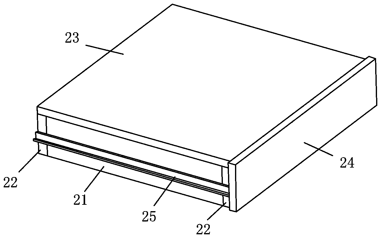
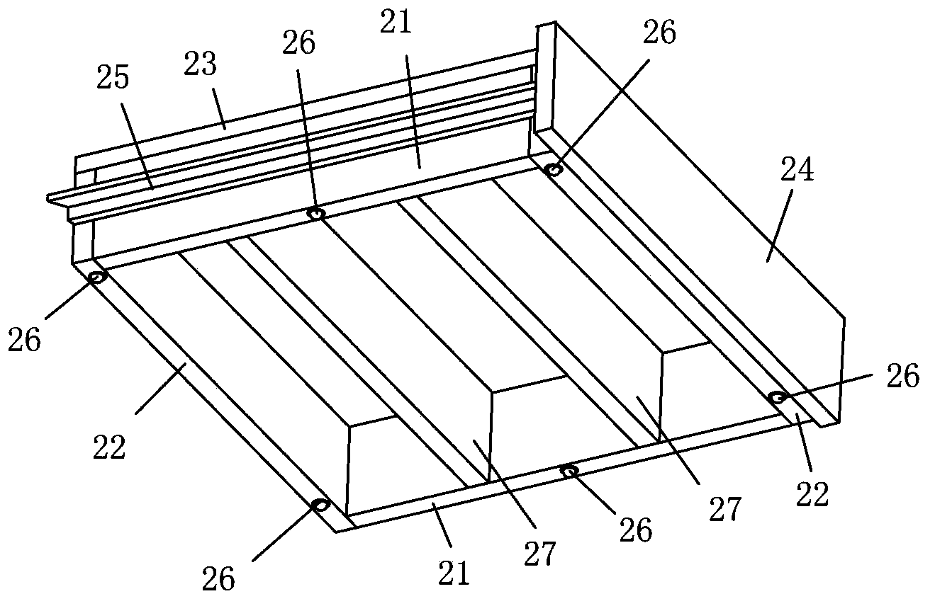
[0016] The three-dimensional structure of an embodiment of the foot pad of the kitchen cabinet of the present invention, as figure 1 and figure 2 As shown, it has two upright plates 21 on the left and right and two upright plates 22 on the front and back to form a rectangular frame, and an end panel 23 is fixed on the upper end of the frame; A decorative panel 24 protruding slightly from the side. The left and right side plates 21 of the frame are respectively provided with front and rear guide rails 25, and the lower end surface of the frame is provided with two rows of left and right, each with three mounting holes for six mounting holes, and a touch bead 26 is installed in each mounting hole; Two upright stiffener plates 27 are arranged at intervals inside the frame to increase the support for the end panel 23 .

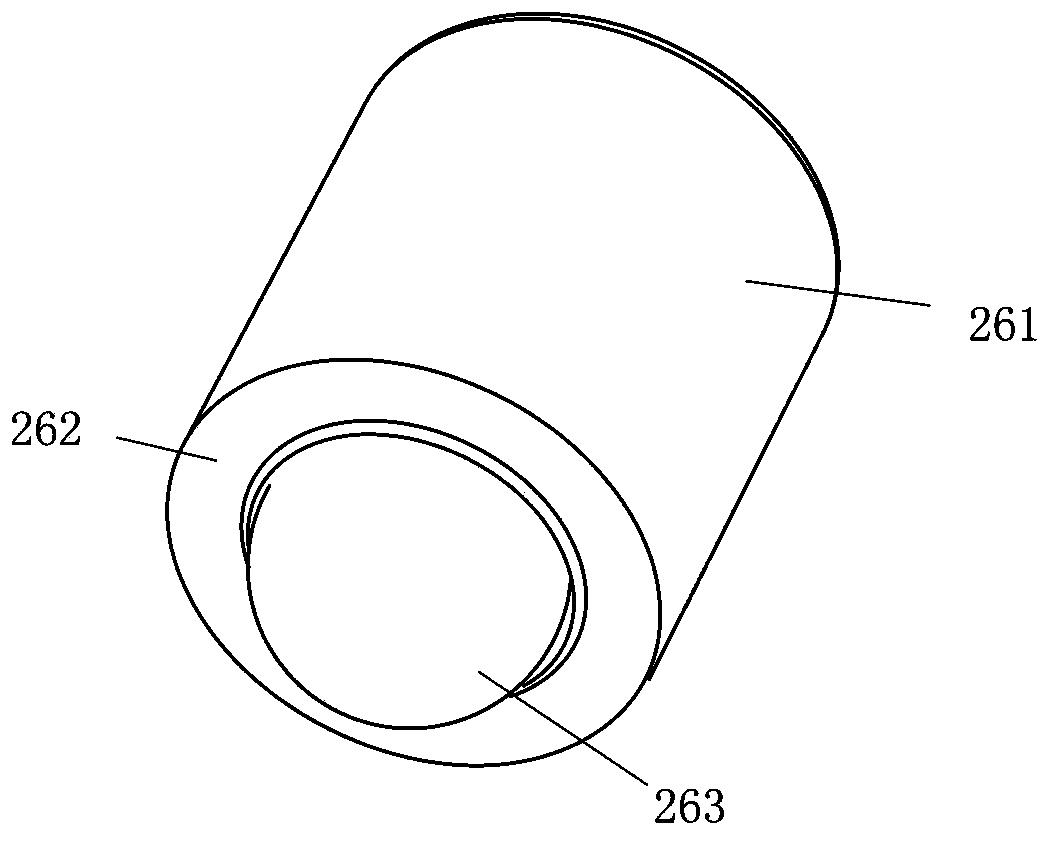
[0017] please see image 3 and Figure 4 The lower end of the housing 261 of the touch ball 26 is an open end 262, and a spring 265, a diaphragm 266 and a ba...


PUM


Abstract

The invention relates to a bottom stand for kitchen cabinets and relates to a furniture part. The bottom stand is characterized in that a rectangular frame is composed of four vertical boards, an end board is fixed at the upper end of the frame, left and right sides of the frame are provided with front and back guide rails respectively, the two guide rails are inserted onto and hung to corresponding lower guide rails of a kitchen cabinet respectively, the lower end of the frame is provided with at least three mounting holes, a ball is mounted in each mounting hole, the open end of a housing of each ball faces down, and a spring in each housing downwardly pushes one ball inside the open end of the housing.

Description

technical field [0001] The invention relates to a part of furniture, in particular to a part of a kitchen cabinet. Background technique [0002] Because people of different heights are cooking in front of the kitchen cabinet, the heights of their arms above the range are also different. Usually the height of kitchen cabinets is designed according to the height of men of middle and upper stature, so as to take into account most people. Therefore, when a woman with a low stature is cooking in front of the kitchen cabinet, the height of her arm above the stove is too low, and she is too close to the frying pan when cooking, which is very uncomfortable. So it is necessary to stand on the foot pads to increase this height and facilitate cooking operations. A common foot pad is to use four upright plates to form a rectangular frame, and an end panel is fixed at the upper end of the frame. When in use, operators with low stature can easily perform cooking operations by standing ...

Claims


Application Information

Patent Timeline
IPC IPC(8): A47B77/10A47B77/08
Inventor 潘孝贞
Owner เซี่ยเหมิน โกลเด้นโฮม โค
Why Eureka
Try Eureka