Disc type thin-walled parts milling device

A thin-walled part and disc-type technology, applied in the field of mechanical processing, can solve the problems of affecting the quality of the processed surface, unstable processing process, and aggravated processing deformation, so as to improve milling efficiency, improve the quality of processed surface, and small clamping deformation Effect

Active Publication Date: 2016-05-18
INST OF OPTICS & ELECTRONICS - CHINESE ACAD OF SCI
View PDF7 Cites 0 Cited by
  • Summary
  • Abstract
  • Description
  • Claims
  • Application Information

AI Technical Summary

Problems solved by technology

The disadvantage is: when the clamping force is too small, the parts will rotate in the three jaws during milling; The rigidity of the parts will decrease accordingly, and the processing deformation will increase, which will cause the parts to tremble, affect the quality of the processed surface, and the processing process will be unstable and inefficient

Method used


Image

  • Disc type thin-walled parts milling device
  • Disc type thin-walled parts milling device
  • Disc type thin-walled parts milling device

Examples


Embodiment Construction

[0022] In order to make the purpose, technical solutions and advantages of the present invention clearer, the following in conjunction with specific examples, and with reference to the appended Figure 1 to Figure 4 Shown, the specific embodiment of the present invention will be further described.

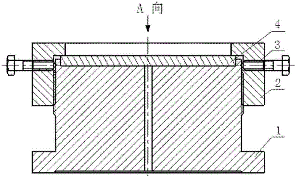
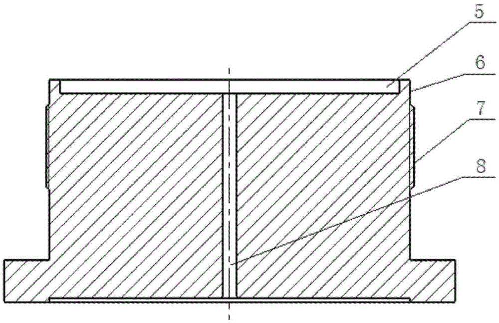
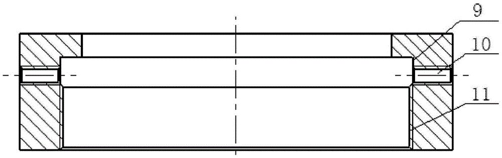
[0023] Such as figure 1 As shown, the disc-type thin-walled part milling device of the present invention includes: a base 1 , a back cap 2 , and two screws 3 . The base 1 is provided with an external thread 7 with a pitch of 1.5 mm, and the back cap 2 is provided with an internal thread 11 with a pitch of 1.5 mm, and the external thread 7 of the base 1 is threadedly connected with the internal thread 11 of the back cap 2, and the back cap 2 is provided with an internal thread 11 with a pitch of 1.5 mm. The cap 2 presses the part 4 to be processed. The screw 3 is screwed into the two threaded holes 10 on the back cap 2, and the screw tightening surface 6 is tightened against the s...


PUM


Abstract

The invention relates to a milling and clamping device for disc type thin-wall parts. The milling and clamping device comprises a base body, a back hat and two screws, wherein one end of the base body is in threaded connection with the back hat, and the screws are screwed into two threaded holes of the back hat to abut on the base body. The milling and clamping device has the advantages of small clamping deformation, reliable performance, low cost, convenient in assembly and disassembly, increases the milling efficiency, and is suitable for difficult-clamping and mass-produced the disc type thin-wall parts.

Description

technical field [0001] The invention belongs to the technical field of mechanical processing, and in particular relates to a device for milling a disc type thin-walled part. Background technique [0002] Aluminum alloy thin-walled parts are widely used in aerospace, precision instruments and other fields due to their light weight and good strength, but their rigidity is poor and clamping is difficult. A large number of production at one time. The clamping method of conventional milling disc-type thin-walled parts is to clamp its outer circle with three claws. The disadvantage is: when the clamping force is too small, the parts will rotate in the three jaws during milling; The rigidity of the parts will decrease accordingly, and the processing deformation will increase, which will cause the parts to tremble, affect the quality of the processed surface, and the processing process will be unstable and inefficient. Contents of the invention [0003] In order to solve the pr...

Claims


Application Information

Patent Timeline
Patent Type & Authority Patents(China)
IPC IPC(8): B23C3/00
Inventor 冯国余伦郭进文常贵胡光志
Owner INST OF OPTICS & ELECTRONICS - CHINESE ACAD OF SCI
Why Eureka
Try Eureka