PC (Poly carbonate) milling cutter for plastics

A technology for milling cutters and plastics, applied in milling cutters, milling machine equipment, manufacturing tools, etc., can solve the problems of affecting product processing quality and inconvenient chip removal, and achieve the effect of facilitating discharge and reducing surface area

Inactive Publication Date: 2014-02-12
SUZHOU WANYI KNIFE IND
View PDF0 Cites 1 Cited by
  • Summary
  • Abstract
  • Description
  • Claims
  • Application Information

AI Technical Summary

Problems solved by technology

Now milling cutters can process various materials. The side edges of some straight-toothed milling cutters are generally vertical, so the contact area between the teeth of the milling cutter is larger. When processing some plastic products, due to the There is friction between the running and the plastic, so that the milling cutter has an increased temperature. Although there is cooling liquid for cooling, there are still plastic chips stuck in the chip groove, and these chips will be squeezed with the milling cutter running in the milling cutter. On the chip groove on the rear side of the cutting edge, it will cause inconvenience in chip removal and affect the processing quality of the product

Method used


Image

  • PC (Poly carbonate) milling cutter for plastics
  • PC (Poly carbonate) milling cutter for plastics

Examples


Embodiment Construction

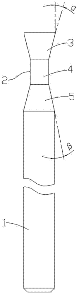
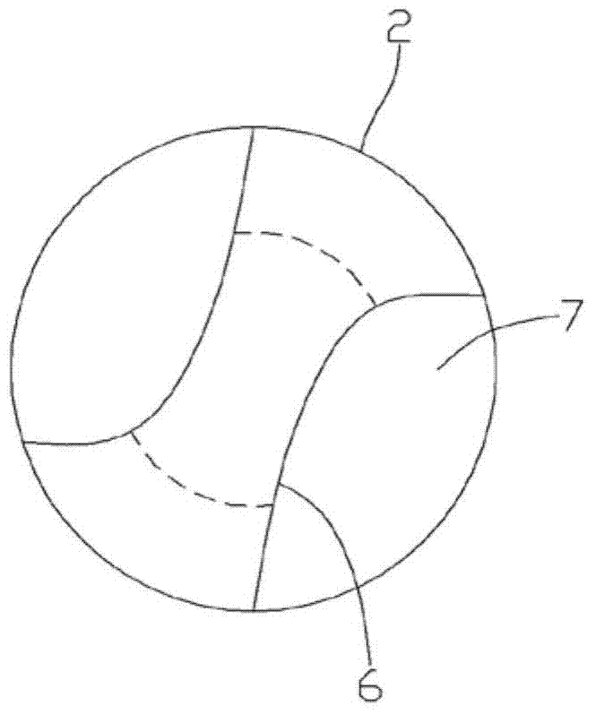
[0013] See figure 1 with figure 2 As shown: the plastic PC milling cutter of the present invention includes a handle 1, a cutter head 2 is formed on the handle 1, and the cutter head 2 is composed of a dovetail groove-shaped blade connecting portion 5, a vertical second blade portion 4 and an inverted dovetail The grooved first blade part 3 is formed, the blade connecting part 5 is formed on the handle 1, and the two ends of the second blade part 4 are respectively connected on the blade connecting part 5 and the first blade part 3, and the first blade There are two straight-toothed knife teeth 6 in the shape of an ax head on the top surface of the part 3, and a chip flute 7 is formed between two adjacent knife teeth 6, and the said knife teeth 6 run through the first knife edge part 3 and the second knife edge part 4 .

[0014] The included angle α between the side edge formed on the second blade portion 4 of the cutter tooth 6 and the central axis of the cutter head 2 is ...


PUM


Abstract

The invention discloses a PC (Poly carbonate) milling cutter for plastics. The PC milling cutter comprises a cutter handle, wherein a cutter bit is formed on the cutter handle and is composed of a dovetail-groove-shaped cutting edge connecting part, a second vertical cutting edge part and a first inverted-dovetail-groove-shaped cutting edge part; the cutting edge connecting part is formed on the cutter handle, two ends of the second cutting edge part are connected on the cutting edge connecting part and the first cutting edge part respectively, two axe-shaped straight-tooth-shaped cutter teeth are formed on the top end surface of the first cutting edge part, a chip trough is formed between the adjacent cutter teeth, and the cutter teeth run through the first cutting edge part and the second cutting edge part. According to the PC milling cutter, the side edge of the milling cutter for cutting plastics is manufactured into an inwardly inclined shape, the surface area of the chip trough is reduced, and the tooth shape is manufactured into the axe shape, so that the large chip trough is formed, plastic cuttings can be discharged conveniently, and the cuttings cannot influence the processing quality while the milling cutter works.

Description

Technical field: [0001] The invention relates to the technical field of milling cutters, and more specifically relates to plastic PC milling cutters. Background technique: [0002] Milling cutters are an important tool used in modern industrial machining. The current milling cutters can be divided into single-end milling cutters, two-edge milling cutters and common three-edge milling cutters according to the cutting edge. Now milling cutters can process various materials. The side edges of some straight-toothed milling cutters are generally vertical, so the contact area between the teeth of the milling cutter is larger. When processing some plastic products, due to the There is friction between the running and the plastic, so that the milling cutter has an increased temperature. Although there is cooling liquid for cooling, there are still plastic chips stuck in the chip groove, and these chips will be squeezed with the milling cutter running in the milling cutter. On the c...

Claims


Application Information

Patent Timeline
Patent Type & Authority Applications(China)
IPC IPC(8): B23C5/02
Inventor 欧阳恩
Owner SUZHOU WANYI KNIFE IND
Why Eureka
Try Eureka