Supercharge Your Innovation With Domain-Expert AI Agents!

Force-controlled electric hand

An electric motor and direct motion technology, which is applied in the direction of program control of manipulators, electric components, and control of mechanical energy, can solve problems such as difficult to detect gripping force, swelling, and changes with good accuracy and stability

Active Publication Date: 2014-02-12
FANUC LTD
View PDF7 Cites 20 Cited by
  • Summary
  • Abstract
  • Description
  • Claims
  • Application Information

AI Technical Summary

Problems solved by technology

[0005] However, the modulus of elasticity of the elastic member described in JP2011-194523A tends to change due to temperature, and there is a hysteresis characteristic between elongation and contraction
In addition, material properties tend to change over time, and there is also concern about swelling due to penetration of lubricating oil and water.
Therefore, it is difficult to accurately and stably detect the gripping force

Method used


Image

  • Force-controlled electric hand
  • Force-controlled electric hand
  • Force-controlled electric hand

Examples


no. 1 approach

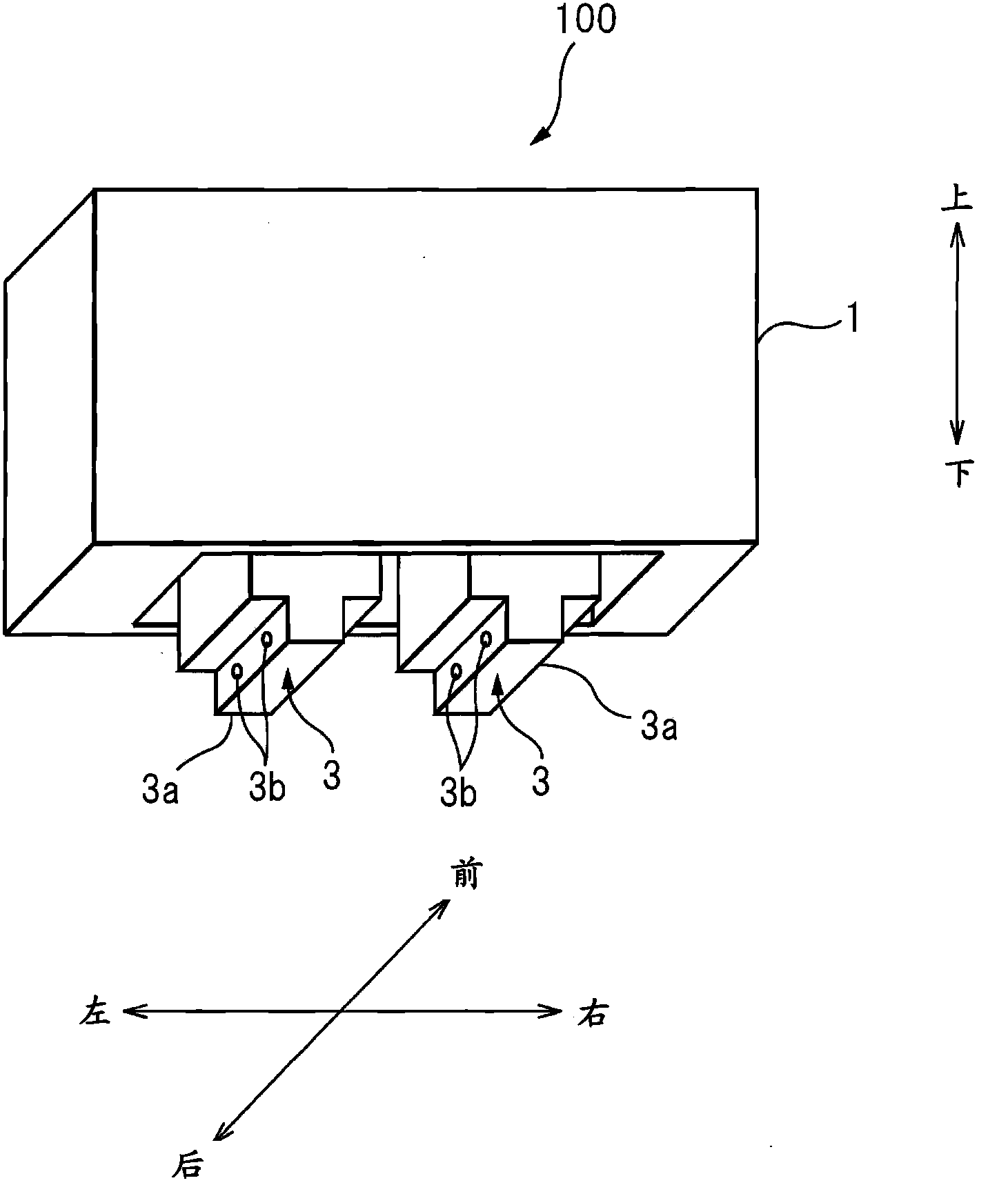
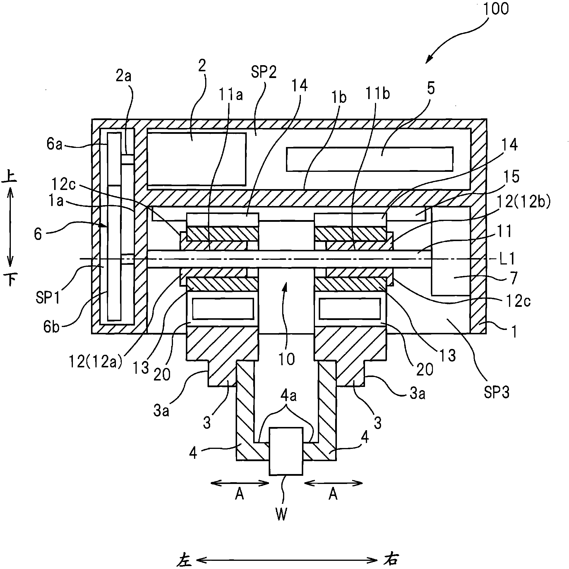
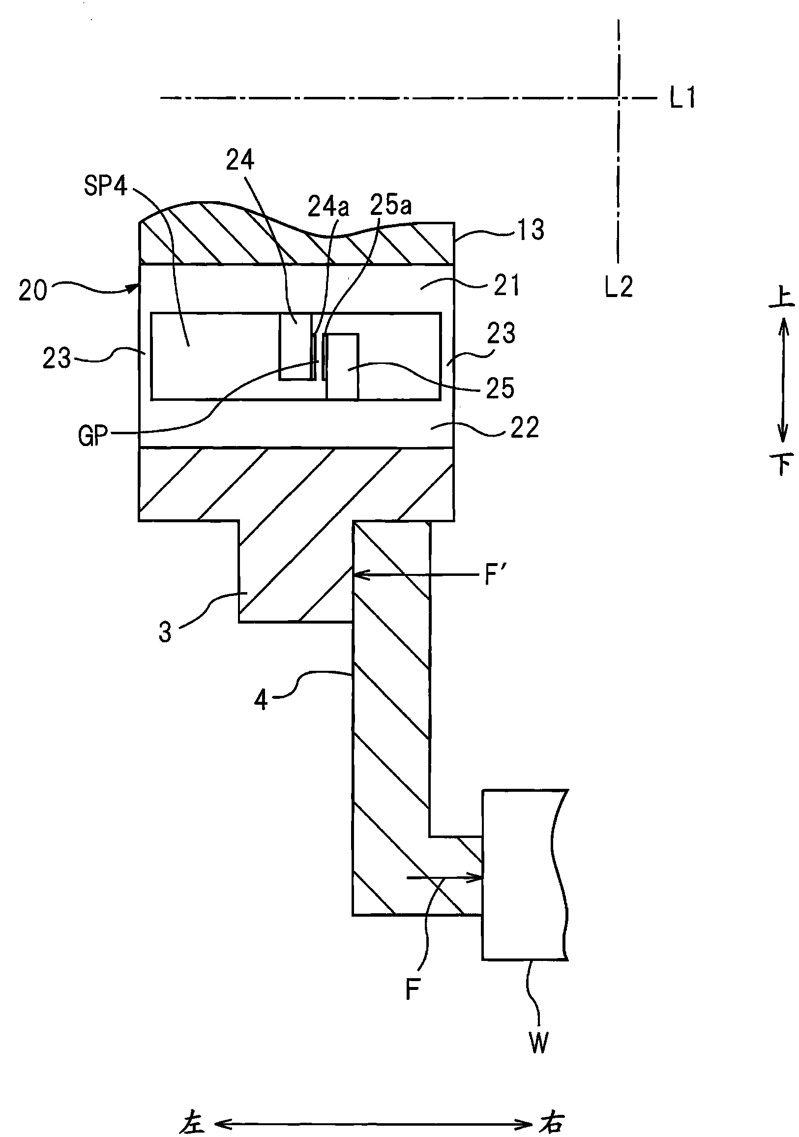
[0013] Below, refer to Figure 1 ~ Figure 3 A first embodiment of the present invention will be described. figure 1 It is a perspective view showing the overall structure of a force control electric hand 100 (hereinafter, may be simply referred to as an electric hand) according to the first embodiment of the present invention. This electric hand 100 is attached to, for example, an arm tip of an industrial robot to grasp an object to be grasped (hereinafter, sometimes simply referred to as an object), and has a pair of fingers that can be opened and closed (refer to figure 2 ),but figure 1 Its illustration is omitted.

[0014] In addition, in the following, for the convenience of description, three mutually orthogonal directions shown in the drawings are defined as the front-rear direction, the left-right direction, and the up-down direction, and the configuration of each part will be described based on these definitions. The left-right direction is a direction in which a p...

no. 2 approach

[0046] refer to Figure 4 A second embodiment of the present invention will be described. The aspect in which the second embodiment differs from the first embodiment in particular lies in the structure of the finger base 3 . That is, in the first embodiment, the pair of finger bases 3 are configured to be movable in the left and right directions as movable finger bases, but in the second embodiment, only the pair of finger bases 3 A composition of is able to move. Such an electric hand 100 is called a single-opening hand.

[0047] Figure 4 It is a sectional view showing the structure of main parts of the electric hand 100 of the second embodiment. Additionally, for figure 2 The same parts are given the same symbols, and the points different from the first embodiment will be mainly described below. Such as Figure 4 As shown, among the pair of left and right force sensors 20 , the right force sensor 20 is fixed to the lower surface of the rotation detector 7 . Therefore...


PUM


Abstract

The invention provides a force-controlled electric hand comprising a rotary-linear motion conversion mechanism for converting the rotary motion from an electric motor to the linear motion; a pair of finger bases which moves linearly in parallel with a first axial line through the rotary-linear motion conversion mechanism by power from the electric motor; a pair of fingers fixed to the pair of finger bases to grip a target workpiece (W) by linear motion of the movable finger base; and a force sensor provided at least at one of the pair of finger bases to detect gripping force of the pair of fingers. The force sensor has a pair of parallel beams extending in parallel with a second axial line vertical to the first axial line and detects the gripping force (F) based on an amount of displacement of the parallel beams in a direction of the first axial line.

Description

technical field [0001] The present invention relates to a force-controlled electric hand that grasps a grasping object by driving fingers with electric motors. Background technique [0002] As such a force-controlled electric hand, a robot hand mounted on an industrial robot is known. When grasping an object to be grasped using a robot hand, it is preferable that the grasping force can be easily adjusted in order to cope with objects to be grasped of various shapes. For example, Japanese Unexamined Patent Application Publication No. 2011-183513 (JP2011-183513A) describes a gripping device in which an electric motor drives a rotation-to-direction conversion mechanism through a reduction mechanism, and has an opening and closing operation through the rotation-to-direction conversion mechanism. a pair of fingers. The device described in this JP2011-183513A adjusts the motor current according to the characteristics previously determined by experiments or the like, thereby adju...

Claims


Application Information

Patent Timeline
Patent Type & Authority Applications(China)
IPC IPC(8): B25J15/02B25J13/00
CPCH02K7/00B25J15/026B25J9/1612B25J13/085Y10S294/907B25J13/082B25J15/0253
Inventor 坂野哲朗
Owner FANUC LTD
Features
  • R&D
  • Intellectual Property
  • Life Sciences
  • Materials
  • Tech Scout
  • Unparalleled Data Quality
  • Higher Quality Content
  • 60% Fewer Hallucinations
Learn More