Solar movable water layer exchange and oxygenation device

An oxygen-enhancing device and solar energy technology, applied in water aeration, chemical instruments and methods, water/sludge/sewage treatment, etc. problems, to achieve the effect of reducing the amount of equipment configuration, overcoming the small scope of action, and reducing the number of installations

Active Publication Date: 2015-03-18
FISHERY MACHINERY & INSTR RES INST CHINESE ACADEMY OF FISHERY SCI
View PDF5 Cites 0 Cited by
  • Summary
  • Abstract
  • Description
  • Claims
  • Application Information

AI Technical Summary

Problems solved by technology

[0004] First, the traditional mechanical aeration focuses on increasing the contact between the water body and the air to increase the dissolved oxygen level in the water body through mechanical disturbance, and there are problems such as low oxygenation efficiency;
[0005] Second, the traditional aerator is basically a fixed structure. Although it is easy to install, the oxygenation range is limited, and it can only increase the dissolved oxygen level in local water bodies. Continuous operation has problems such as reduced oxygenation efficiency and increased energy consumption after oxygen saturation. ;
[0006] Third, the traditional oxygenation machinery ignores the utilization of photosynthesis oxygenation, and the efficiency of oxygenation is not high;
[0007] Fourth, the traditional aeration machine does not make enough use of the exchange of oxygen in the upper and lower water layers, which is not conducive to the balance of dissolved oxygen in the water body

Method used


Image

  • Solar movable water layer exchange and oxygenation device
  • Solar movable water layer exchange and oxygenation device
  • Solar movable water layer exchange and oxygenation device

Examples


Embodiment Construction

[0045] The present invention will be further described below in conjunction with accompanying drawing.

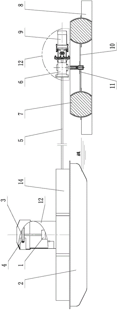
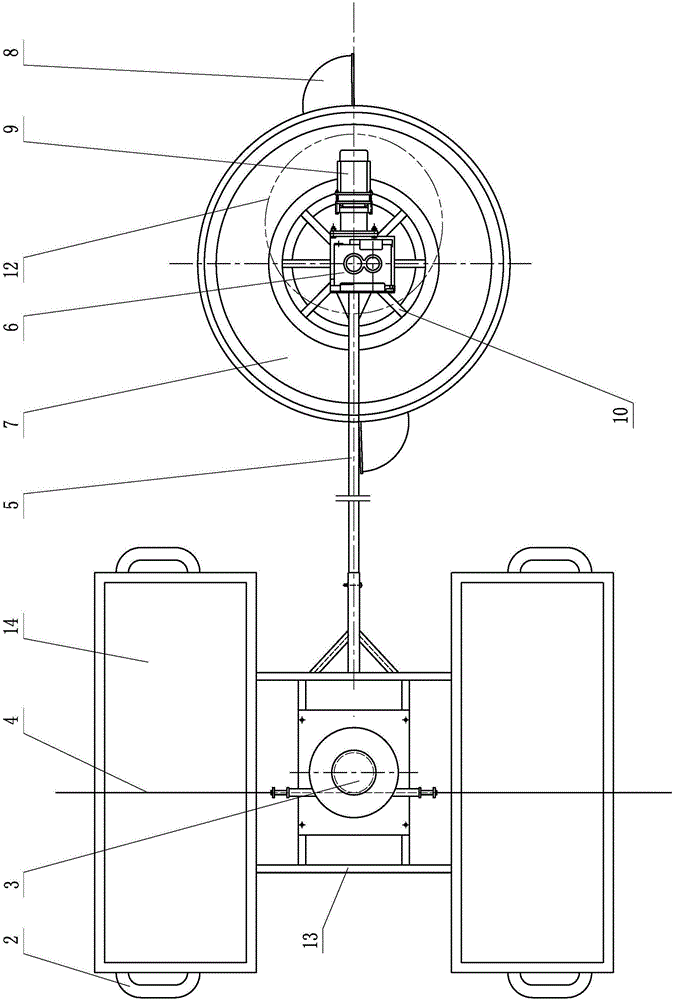
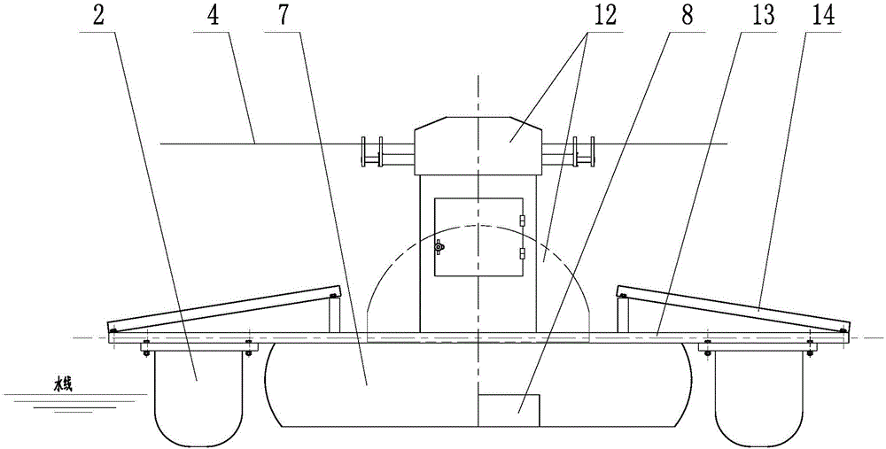
[0046] The solar power boat 2 is composed of two parallel boat-shaped injection-molded floating bodies, and the two boat-shaped injection-molded floating bodies are connected as a whole through a horizontal mounting bracket 13. The first motor 1 powered by the solar power generation component is arranged in a horizontal rotation mode on the solar power boat 2. On the mounting bracket 13 at the central position, the solar powered boat 2 can rotate horizontally around the first motor 1 .

[0047] The output shaft of the first motor 1 protrudes vertically upwards, and a reel 3 is fixed horizontally at the protruding end. After the horizontal guide rope 4 is wound on the reel 3 for one circle, the two ends are respectively fixed on both sides of the aquaculture pond. On the pond ridge; 2 contact switches are installed at intervals on the guide rope 4, and the contact switch is ...


PUM


Abstract

A solar movable water layer exchange and oxygenation device is characterized in that a first motor of which power is supplied by a solar power generation component is arranged on a solar power boat in a horizontal rotation manner; an output shaft of the first motor extends out upwards vertically, a trolling reel is horizontally fixed at an end part of the first motor; after a guiding rope is wound one circle around the trolling reel, the two ends of the guiding rope are fixed on two side pond ridges of a cultivation pond; the solar power ship and a gearbox are in rigid connection with two ends of a connecting rod; a vertical downward output shaft of the gearbox is connected to the circumferential center of a water stirring floating body; a plurality of water stirring wings are circumferentially mounted on the outer edge of the water stirring floating body; a second motor of which power is supplied by the solar power generation component is arranged on an input shaft of the gearbox; the position of the output shaft of the gearbox diverges from the center-of-gravity position of the combined unit of the gearbox and the second motor. The device uses solar energy as power, can save a great amount of electrical energy, reduces the number of oxygenation devices mounted in an aquiculture water body, has the characteristics of enlarged oxygenation area and wide covering surface, realizes light control and independent operation, and can greatly improve the influence of photosynthesis on the water body.

Description

technical field [0001] The invention relates to the field of aquaculture, in particular to pond culture aeration equipment. Background technique [0002] Since the 1970s, the invention of water aeration machinery has greatly promoted the development of my country's aquaculture industry, making my country's aquaculture output quickly become the world's first, and played a huge role in increasing the supply of aquatic products in the market and meeting people's living standards. role. At present, the aerator has become the most widely promoted and the largest number of fishery machinery in the country. It is a well-known fish farming machine with Chinese characteristics in high-yield pond fish farming areas. Aerators can not only increase dissolved oxygen in water, but also remove harmful gases such as ammonia and hydrogen sulfide, and are widely used. In recent years, with the development of aquaculture oxygenation technology, various types of aeration machines have emerged,...

Claims


Application Information

Patent Timeline
Patent Type & Authority Patents(China)
IPC IPC(8): C02F7/00
CPCY02W10/10
Inventor 刘兴国张拥军邹海生吴宗凡唐荣朱浩田昌凤顾兆俊徐国昌
Owner FISHERY MACHINERY & INSTR RES INST CHINESE ACADEMY OF FISHERY SCI
Why Eureka
Try Eureka