Oil pan structure of engine

A technology of oil pan and engine, which is applied in the direction of engine lubrication, engine components, machines/engines, etc. It can solve problems such as the temperature rise of lubricating oil, the difficulty of removing the oil plug inside the oil drain plug, and the complicated structure of the oil drain plug. , to achieve the effect of suppressing the decline of lubricating performance

Inactive Publication Date: 2014-02-12
MITSUBISHI MOTORS CORP +1
View PDF6 Cites 2 Cited by
  • Summary
  • Abstract
  • Description
  • Claims
  • Application Information

AI Technical Summary

Problems solved by technology

[0007] However, as in the aforementioned Patent Document 1, if the oil drain hole is simply provided on the inner oil pan, lubricating oil always circulates between the inner oil pan and the outer oil pan. The problem of preventing the temperature rise of the lubricating oil in the internal oil pan
[0008] In addition, when the oil drain plug is composed of an internal oil plug and an external oil plug as described above, the structure of the oil drain plug is complicated, which causes an increase in cost, and at the same time, it is difficult to remove the oil drain plug, especially the internal oil plug. , the problem of increasing the number of processes during oil discharge

Method used


Image

  • Oil pan structure of engine
  • Oil pan structure of engine
  • Oil pan structure of engine

Examples


Embodiment Construction

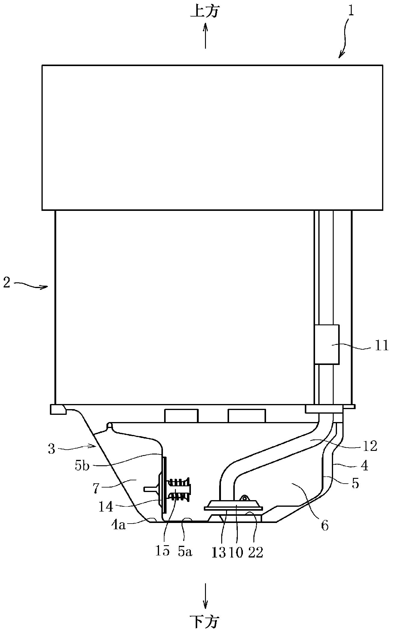
[0027] Below, will be based on Figure 1 to Figure 4 The illustrated embodiments illustrate the invention. figure 1 It is a vertical cross-sectional view showing an outline of the structure of the engine 1 according to the present embodiment employing the oil pan structure of the present invention. In the lower portion of the cylinder block 2 of the engine 1 according to the present embodiment, an oil pan 3 for storing lubricating oil is provided.

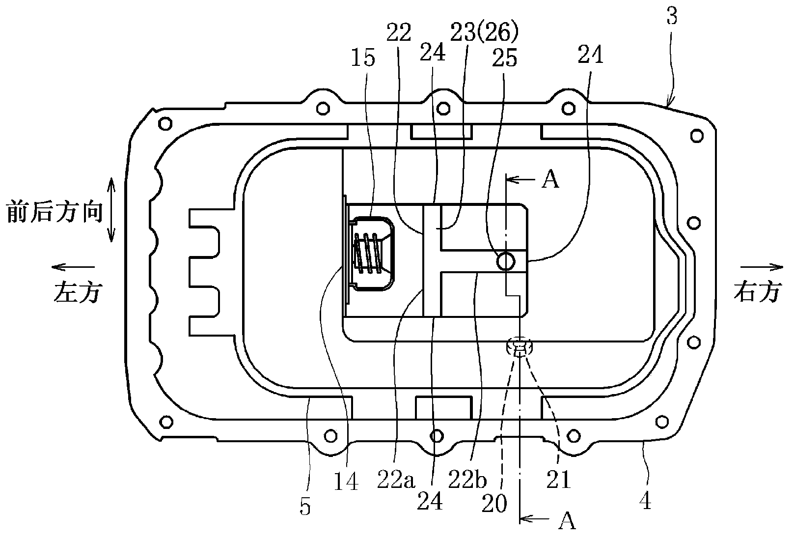
[0028] The oil pan 3 is an oil pan 3 having a double structure composed of an outer oil pan 4 and an inner oil pan 5 with an upper opening having a substantially rectangular shape.

[0029] The inner oil pan 5 is smaller than the outer oil pan 4, is disposed in the outer oil pan 4, and has a first storage chamber 6 inside which lubricating oil can be stored.

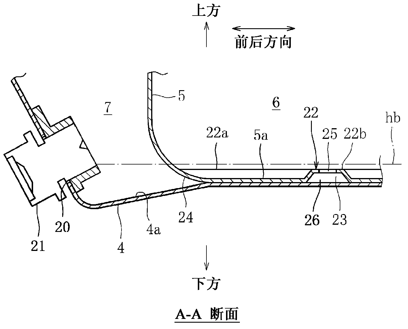
[0030] The bottom of the inner oil pan 5 is placed on the bottom wall 4a of the outer oil pan 4, and partly connected. The inner oil pan 5 is formed laterally smaller than...


PUM


Abstract

Provided is an oil pan structure of an engine, which can easily exhaust oil from an oil pan in a simple structure and meanwhile, suppresses lubricating oil from circulating between an inner oil pan and an outer oil pan when engine heating is carried out. The oil pan is provided with the inner oil pan 5 on the bottom wall of the outer oil pan 4 to form an oil pan 3, a protruding part 22 protruding upwards in a T shape is formed on the bottom wall of the inner oil pan 5, a local gap is arranged between the bottom wall of the outer oil pan 4 and the bottom wall of the inner oil pan 5, and the bottom wall 5a of the inner oil pan 5 above the gap is provided with a communicating hole 5a, and meanwhile, an opening 24 opened with respect to a second storage chamber and a communicating path 23 communicating a first storage chamber 6 and the second storage chamber 7 are arranged at the end of the gap and the position separating from the communicating hole, and an oil outlet facing the second storage chamber 7 is arranged in the outer oil pan 4.

Description

technical field [0001] The present invention relates to an oil pan having a double structure of an inner oil pan and an outer oil pan. Background technique [0002] As an oil pan provided at a lower portion of an engine to store lubricating oil, an oil pan having a double structure in which an inner oil pan is provided in an outer oil pan is widely known. [0003] In the engine having the oil pan of the double structure, a first storage chamber in which lubricating oil can be stored is formed in the inner oil pan, and a storage chamber in which lubricating oil can be stored is formed between the inner oil pan and the outer oil pan. Second storage room. Moreover, it becomes a structure in which lubricating oil is sucked out from the first storage chamber through a strainer, supplied to parts requiring lubrication in the engine, and then returned to the first storage chamber for circulation. The first storage chamber and the second storage chamber The chambers are communicab...

Claims


Application Information

Patent Timeline
Patent Type & Authority Applications(China)
IPC IPC(8): F01M11/00
Inventor 吉田均吉田哲也水野惠
Owner MITSUBISHI MOTORS CORP
Why Eureka
Try Eureka