Differential pressure type pneumatic adjusting rotating device

A pneumatic adjustment and rotation device technology, applied in the direction of charging system, exhaust gas recirculation, engine components, etc., can solve the problems of complex control system and achieve the effect of reasonable design and simple structure

Inactive Publication Date: 2014-02-12
刘洪涛
View PDF1 Cites 2 Cited by
  • Summary
  • Abstract
  • Description
  • Claims
  • Application Information

AI Technical Summary

Problems solved by technology

[0003] After searching the existing technical literature, it is found that Chinese patent number ZL200410063439.5, patent name: electronic exhaust gas recirculation gas control device, this patent technology provides a device for controlling the exhaust gas recirculation rate of the engine, which can better Taking into account the medium and high speed conditions of the engine; but the change of the exhaust gas recirculation rate is realized through a special control structure, which makes the control system more complicated

Method used


Image

  • Differential pressure type pneumatic adjusting rotating device
  • Differential pressure type pneumatic adjusting rotating device
  • Differential pressure type pneumatic adjusting rotating device

Examples


Embodiment

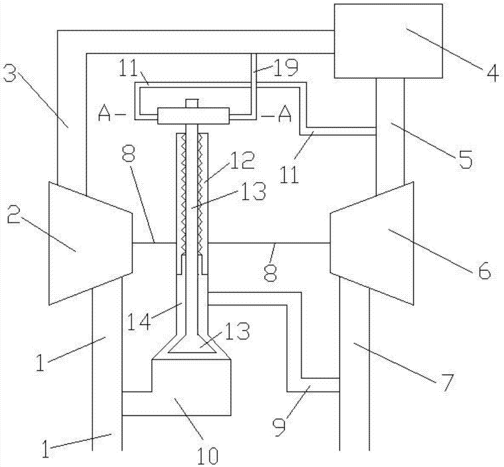
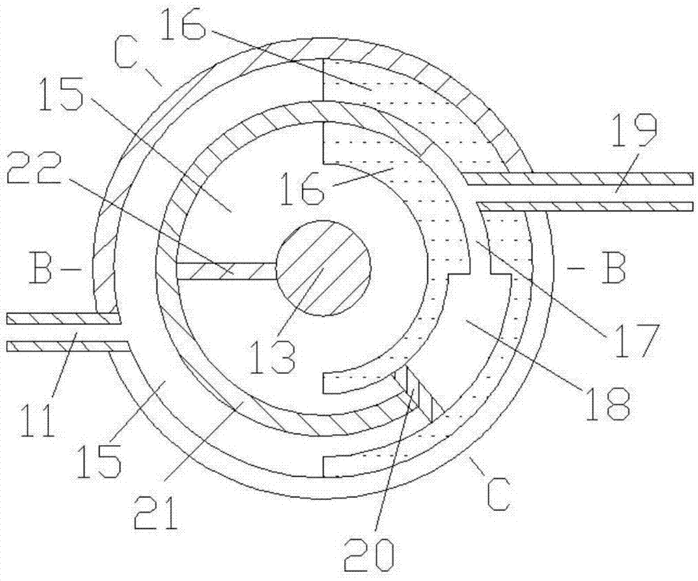
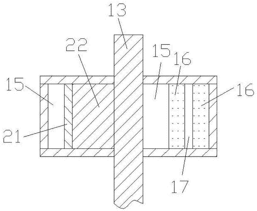
[0015] Such as Figure 1 to Figure 4 Shown, the present invention comprises compressor intake pipe 1, compressor 2, engine intake pipe 3, engine 4, engine exhaust pipe 5, turbine 6, turbine exhaust pipe 7, connecting shaft 8, first connecting pipe 9, the first Second connecting pipe 10, third connecting pipe 11, valve seat 12, valve body 13, volume cavity 15, fixed body 16, first through pipe 17, second through pipe 18, fourth connecting pipe 19, partition 20, rotating Body 21 and connecting plate 22, the air inlet and outlet of compressor 2 are connected with the air outlet of compressor inlet pipe 1 and the air inlet of engine inlet pipe 3 respectively, and the air inlet and outlet of engine 4 are respectively connected with the air outlet of engine inlet pipe 3, The air intake of the engine exhaust pipe 5 is connected, the air inlet and outlet of the turbine 6 are respectively connected with the air outlet of the engine exhaust pipe 5, and the air intake of the turbine exha...


PUM


Abstract

The invention provides a differential pressure type pneumatic adjusting rotating device in the technical field of mechanical design. The differential pressure type pneumatic adjusting rotating device comprises a gas compressor, an engine, a turbine, connecting pipes, a valve seat, a valve body, a rotating shaft, a containing cavity, a fixed body, penetrating pipes, a partition board, a rotating body and a connecting board. One end of the rotating body extends into the first penetrating pipe and is in sealing contact with the wall face of the first penetrating pipe, the other end of the rotating body is fixedly combined with the partition board, the two ends of the first connecting pipe are communicated with a gas inlet of the containing cavity and a gas exhausting pipe of the turbine respectively, and the two ends of the second connecting pipe are communicated with a gas outlet of the containing cavity and a gas inlet pipe of the gas compressor respectively. When the pressure of the gas inlet pipe of the engine is large, the rotating body drives the valve body to rotate clockwise, the low-pressure gas exhausting recirculation rate of the engine is large, and the detonation pressure of the engine is low; when the pressure of the gas inlet pipe of the engine is small, the rotating body drives the valve body to rotate anticlockwise, the low-pressure gas exhausting recirculation rate of the engine is small, and the oil consumption of the engine is low. The differential pressure type pneumatic adjusting rotating device is reasonable in design, simple in structure, and suitable for a low-pressure gas exhausting recirculation system of a supercharged engine.

Description

technical field [0001] The invention relates to a low-pressure exhaust gas recirculation system in the technical field of mechanical design, in particular to a differential-pressure pneumatic regulating rotary device. Background technique [0002] Harmful emissions from engines are a major source of air pollution. With the increasing importance of environmental protection, the goal of reducing harmful emissions from engines has become an important direction for engine development in the world today. With the world's consumption of petroleum products increasing year by year, international oil prices remain high, and the economy of diesel vehicles is becoming more and more prominent, which makes diesel engines occupy an increasingly important position in vehicle power. Therefore, it is the primary task of diesel engine designers to carry out research on the control methods of harmful emissions from diesel engines. The low-pressure exhaust gas recirculation system is to send a...

Claims


Application Information

Patent Timeline
Patent Type & Authority Applications(China)
IPC IPC(8): F02D9/08F02M35/10F02M25/07F02M26/10
CPCY02T10/121
Inventor 刘洪涛
Owner 刘洪涛
Why Eureka
Try Eureka