Refrigerator and freezer

A refrigerator and condenser technology, which is applied in the field of refrigerating and refrigerating refrigerators, can solve the problems of difficulty in increasing the condensation capacity, reducing air circulation, and difficulty in ensuring the condensation capacity of the main body of the refrigerating and refrigerating refrigerator.

Active Publication Date: 2014-02-12
MITSUBISHI ELECTRIC CORP
View PDF8 Cites 3 Cited by
  • Summary
  • Abstract
  • Description
  • Claims
  • Application Information

AI Technical Summary

Problems solved by technology

[0008] In the aforementioned conventional freezer-refrigerator, since the exhaust port is provided on the back of the machine compartment of the freezer-refrigerator main body, the exhaust port becomes a gap with the wall due to the installation conditions and installation period of the freezer-refrigerator main body. In a narrow or dust-clogged state, the circulation of air is reduced. In this case, it is difficult to ensure the amount of condensation corresponding to the

Method used


Image

  • Refrigerator and freezer
  • Refrigerator and freezer
  • Refrigerator and freezer

Examples


Embodiment approach 1

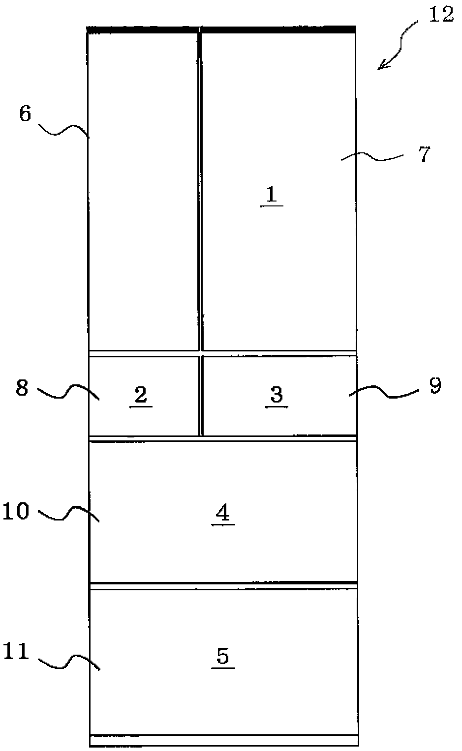
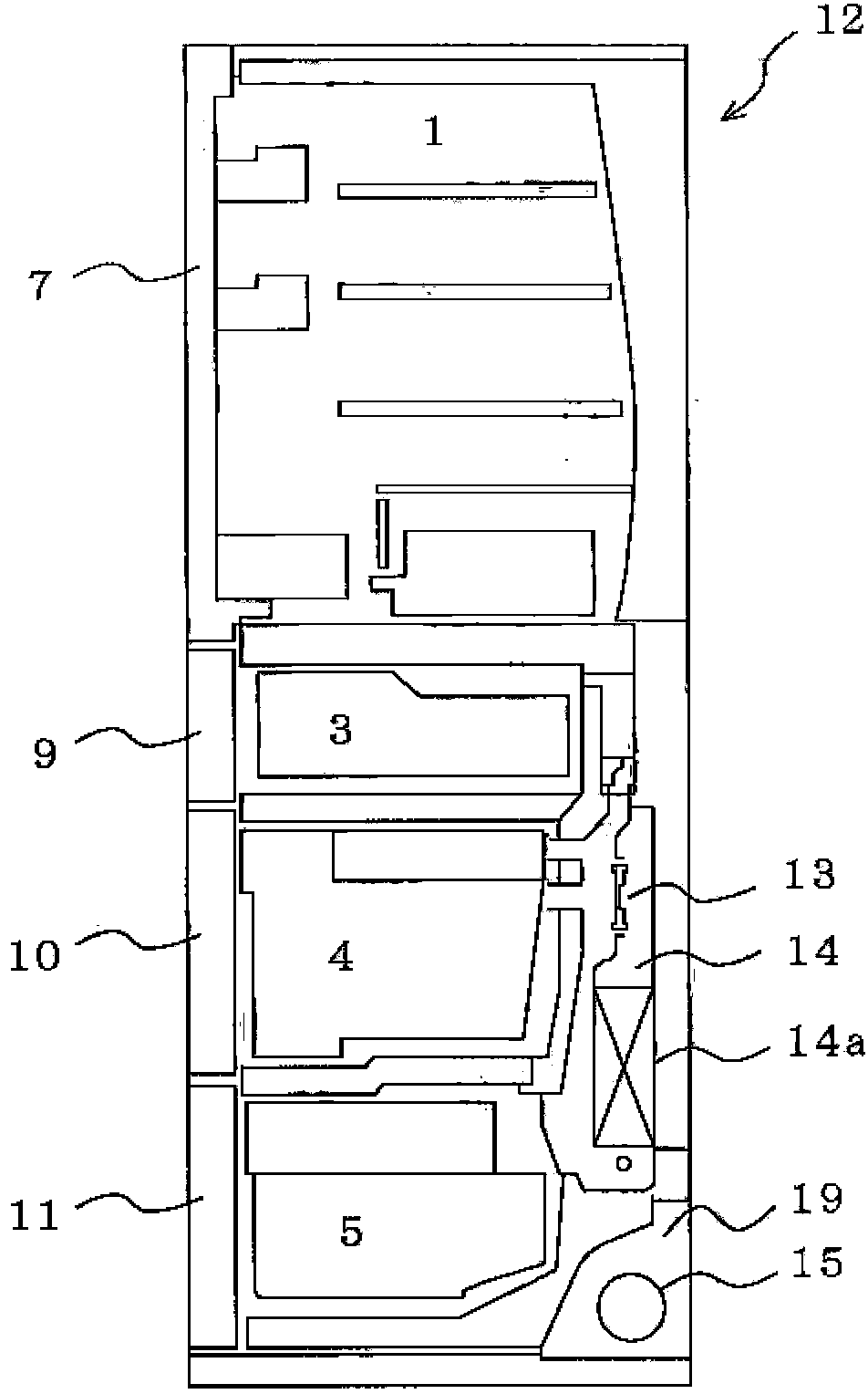
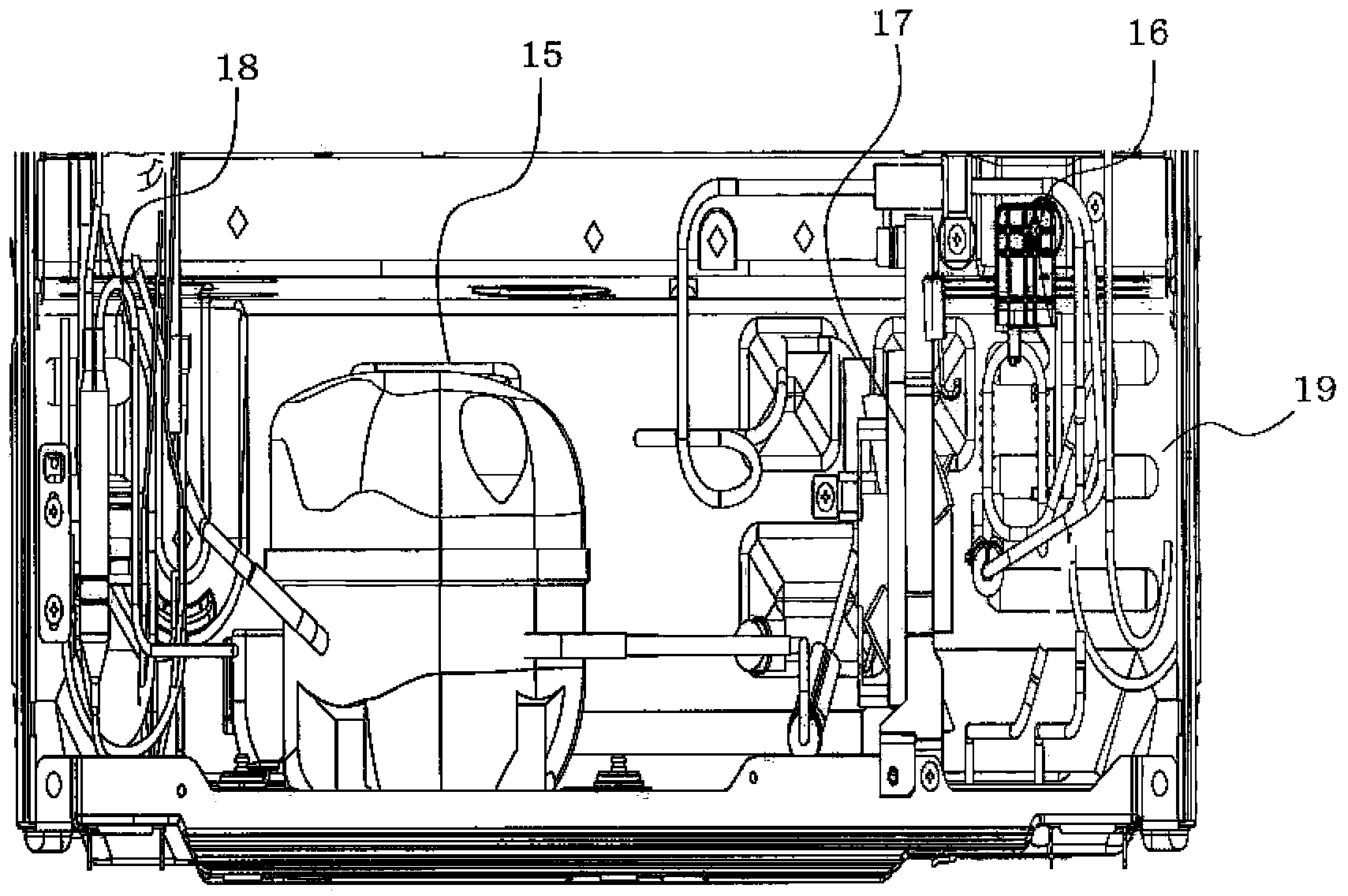
[0031] figure 1 It is a front view of the freezer-refrigerator according to Embodiment 1 of the present invention, figure 2 It is a side sectional view of the freezer-refrigerator according to Embodiment 1 of the present invention, image 3 It is a front view which shows the inside of the machine room provided in the back lower part of the freezer-refrigerator concerning Embodiment 1 of this invention.

[0032] exist Figure 1 to Figure 3 Among them, the main body 12 of the freezer-refrigerator is formed by filling the space between the outer box and the inner box with heat insulating members such as foamed polyurethane. In the main body 12 of the freezer-refrigerator, a plurality of storage chambers with front openings are provided by partition walls integrally formed with the main body 12 of the freezer-refrigerator. For example, a refrigerating chamber 1 is provided on the uppermost layer of the main body 1 of the freezer-refrigerating refrigerator, and an ice-making ch...

Embodiment approach 2

[0049] In Embodiment 2, in addition to the air intake port 21 of the duct 25 , a lower air intake port is provided in the lower cover portion 27 of the duct 25 .

[0050] Figure 7 It is a perspective view which shows the lower cover part of the duct of the freezer-refrigerator which concerns on Embodiment 2 of this invention, Figure 8 It is a side sectional view showing the duct arranged in the lower part of the freezer-refrigerator according to Embodiment 2 of the present invention and the machine room in the lower part of the back, Figure 9 It is a temperature contour diagram in the duct of the freezer-refrigerator in Embodiment 2 of this invention. In addition, the same code|symbol is attached|subjected to the same part as Embodiment 1. As shown in FIG.

[0051] The aforementioned lower suction port 28 is as Figure 7 As shown, it is provided at the bottom of the lower cover portion 27 on the side of the air inflow path 23 . The lower air inlet 28 is formed in a long...


PUM


Abstract

The invention provides a refrigerator and freezer which is not subjected to the main body of the refrigerator and freezer and improves the heat radiation efficiency of a condenser. The refrigerator and freezer comprises a mechanical chamber (19) arranged on the lower portion of the back of the main body, wherein at least one compressor (15) and a blower (17) for the mechanical chamber are arranged in the mechanical chamber; a pipe (25) arranged on the front lower portion of the mechanical chamber of the main body; and a metal wire type condenser (20) in the pipe, wherein the pipe (25) is provided with an air suction port (21) on the right side of the main body, an air inflow path (23) communicating the suction port and an air intake port (19a) of the mechanical chamber and being arranged on the metal wire type condenser (20), an air exhaust port (22) arranged on the front side of the main body and being adjacent to the air suction port (21), and an air flow path (24) communicating the air exhaust port and an air outlet port (19b) of the mechanical chamber.

Description

technical field [0001] The present invention relates to a freezer-refrigerator equipped with a condenser in a lower portion of a freezer-refrigerator body. Background technique [0002] Conventional freezer-refrigerators generally arrange the mechanical chamber equipped with compressors and blowers at the lower back of the main body of the freezer-refrigerator. , The air is sent to the above-mentioned condenser, and the air is discharged from the back of the machine room. [0003] As a representative example, there is a freezer-refrigerator as follows, which is equipped with: a duct that guides the air that has flowed in from the air inlet facing the front of the freezer-refrigerator body to the machine room through the air inlet; The inside of the pipeline is arranged horizontally so as to separate the inside of the pipeline up and down (for example, refer to Patent Document 1). [0004] A plurality of ventilation holes are provided on the plate of the plate condenser, an...

Claims


Application Information

Patent Timeline
IPC IPC(8): F25D19/00F25B39/04
Inventor 卫藤浩中津哲史田代雄亮小林孝
Owner MITSUBISHI ELECTRIC CORP
Why Eureka
Try Eureka