Self-protection H bridge driving circuit

A bridge drive circuit and self-protection technology, which is applied in the field of H bridge drive circuit, can solve the problems of high cost, poor flexibility, and occupying a large PCB area, and achieve the effect of small quantity, simple construction, and high flexibility

Active Publication Date: 2014-02-12
成都威特电喷有限责任公司
View PDF6 Cites 4 Cited by
  • Summary
  • Abstract
  • Description
  • Claims
  • Application Information

AI Technical Summary

Problems solved by technology

[0004] The usual solutions are mainly implemented by using a dedicated driver chip with integrated hardware circuits or using discrete logic devices to build a control circuit, such as IR2110, L298N, TLE5209, etc. The disadvantages of these solutions are relatively high cost and flexibility. Poor, when driving high-power loads, external high-power switching elements are required, which takes up a lot of PCB area

Method used


Image

  • Self-protection H bridge driving circuit
  • Self-protection H bridge driving circuit
  • Self-protection H bridge driving circuit

Examples


Embodiment Construction

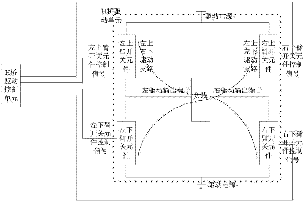
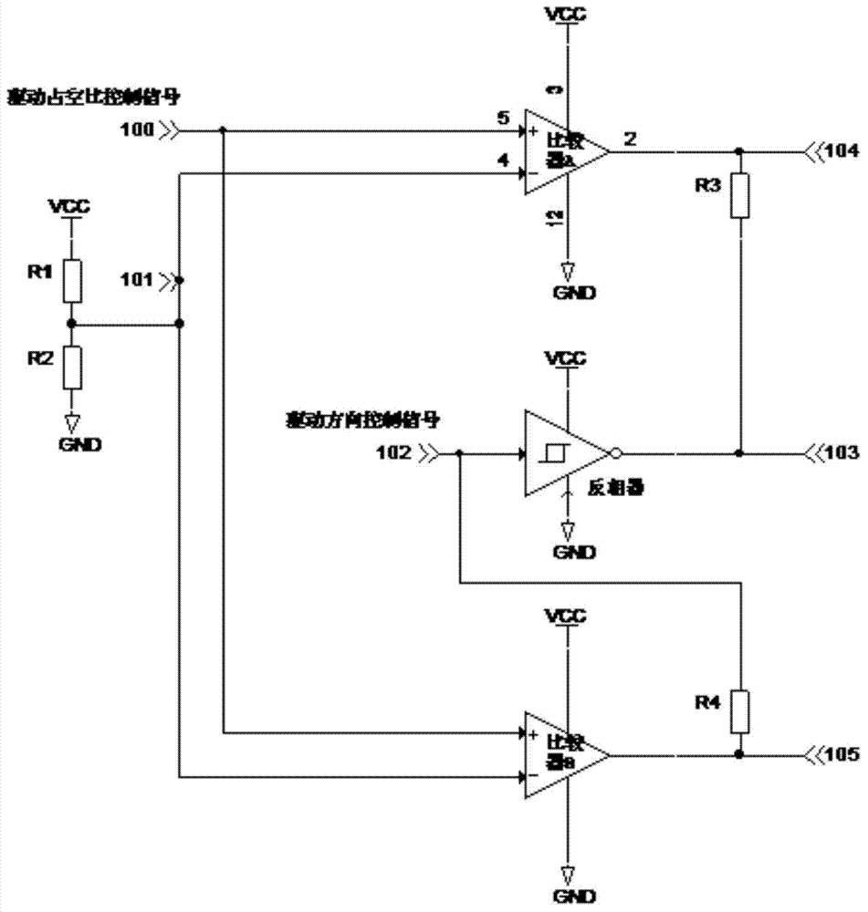
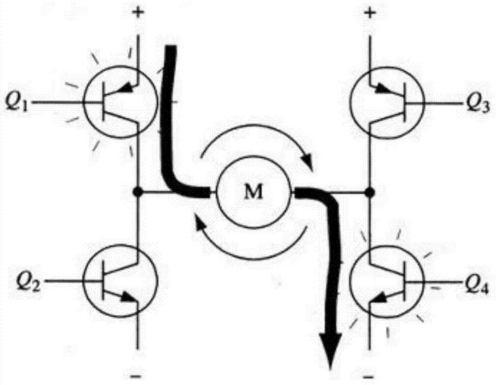
[0013] refer to figure 1 . In the embodiment described below, the self-protection H-bridge drive circuit includes an H-bridge drive control unit and an H-bridge drive unit, wherein the H-bridge drive unit is composed of two drive output terminals, four switch elements, and four switches The components are on the diagonal. The switching elements of the left upper arm and the right lower arm form a left upper right lower driving branch, and the right upper arm and left lower arm switching elements form a right upper left lower driving branch. The above two driving branches are controlled by the H bridge. The drive control unit controls the alternate conduction and controls the direction of the load drive current. In the same drive branch, one switch element controls the output of the load drive current, and the other switch element controls the duty ratio of the load drive current; the H bridge drive unit uses an inverter A phaser channel, two comparator channels and four resi...


PUM


Abstract

The invention provides a self-protection H bridge driving circuit. The self-protection H bridge driving circuit comprises an H bridge driving unit and an H bridge driving control unit. Four switch elements are located on diagonal lines, an upper left and lower right driving branch is formed by the switch element of an upper left arm and the switch element of a lower right arm, an upper right and lower left driving branch is formed by the switch element of an upper right arm and the switch element of a lower left arm, and the H bridge driving control unit controls the two driving branches to be connected alternately and controls the direction of a load current; in the same driving branch, one switch element controls output of the load driving current, and the other switch element controls the duty ratio of the load driving current. When one or two switch elements on one driving branch in the H bridge driving unit are connected, the H bridge driving control unit stops the two switch elements on the other driving branch from being connected, and thus the self-protection function is achieved. Because the independent switch elements are adopted by the H bridge driving unit to built the driving circuit, when different loads are driven by the circuit, the switch elements different in driving capacity can be selected according to currents required for driving the loads, and thus the self-protection H bridge driving circuit is high in flexibility.

Description

technical field [0001] The invention relates to an H bridge driving circuit. technical background [0002] The H-bridge drive circuit gets its name from "H-bridge drive circuit" because its shape resembles the letter H. The 4 switching elements form the 4 vertical legs of the H, and the load being driven is the bar in the H. The H-bridge driving circuit includes 4 switching elements and a load. To make the load work, a pair of switching elements on the diagonal must be turned on at the same time. Depending on the conduction of different switching element pairs, current may flow through the load from left to right or from right to left, thereby controlling the operating state of the load. For example, if image 3 As shown, the triodes Q1, Q2, Q3, and Q4 are used as four switching elements in the H-bridge drive circuit shown in the figure, and the load of the H-bridge drive circuit is a motor. When the Q1 tube and the Q4 tube are turned on, the current passes through the m...

Claims


Application Information

Patent Timeline
Patent Type & Authority Applications(China)
IPC IPC(8): H02M1/32
Inventor 胡洋
Owner 成都威特电喷有限责任公司
Why Eureka
Try Eureka