
Motor deceleration method and motor drive device using the deceleration method

A motor drive and motor technology, applied in the field of motor drive devices, can solve the problems of deceleration capacity discount, frequency value is not easy to determine, etc.

Active Publication Date: 2016-05-25
DELTA ELECTRONICS INC
View PDF4 Cites 1 Cited by
  • Summary
  • Abstract
  • Description
  • Claims
  • Application Information

AI Technical Summary

Problems solved by technology

However, this method is related to the specifications and structure of the motor itself. In other words, the operating point of the frequency will vary depending on the configuration of the motor or the overall system circuit. Therefore, it is not easy to determine the frequency value of the stepwise reduction.
In addition, if the frequency reduction amount is set incorrectly, the deceleration ability of this method will be greatly reduced

Method used


Image

  • Motor deceleration method and motor drive device using the deceleration method
  • Motor deceleration method and motor drive device using the deceleration method
  • Motor deceleration method and motor drive device using the deceleration method

Examples


Embodiment Construction

[0040] A motor deceleration method and a motor driving device according to preferred embodiments of the present invention will be described below with reference to related drawings, wherein the same components will be described with the same reference symbols.

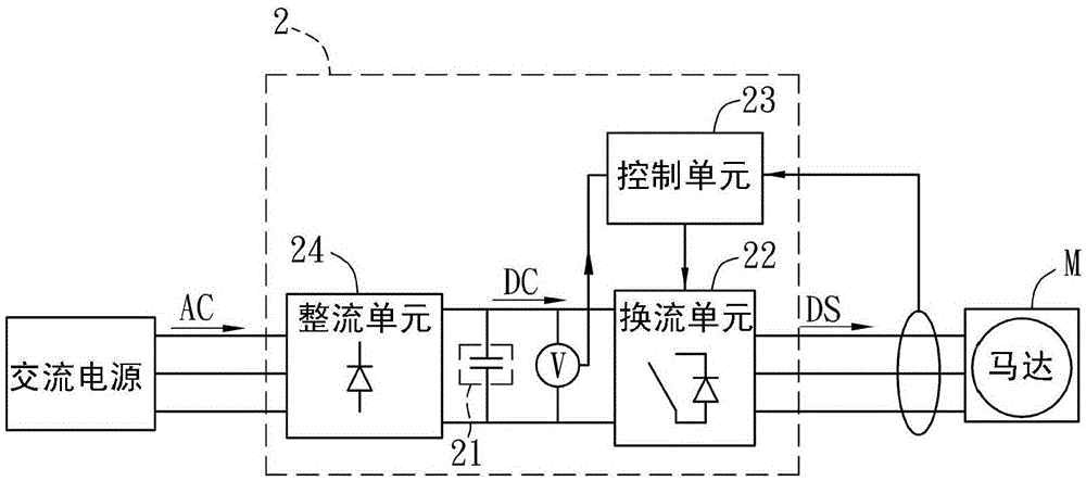
[0041] Please refer to Figure 2A As shown, it is a system block diagram including the motor driving device 2 in a preferred embodiment of the present invention.

[0042] As shown in the figure, the motor driving device 2 of the present invention can receive an AC power source, and can output a driving signal DS to control a motor M to rotate. In addition, the motor deceleration method of the present invention cooperates with the motor drive device 2 to decelerate the motor M to stop. Wherein, in this preferred embodiment, the motor M is a three-phase induction motor, and the AC power source can be a three-phase AC voltage source, such as commercial power.

[0043] The motor driving device 2 includes an energy storag...


PUM


Abstract

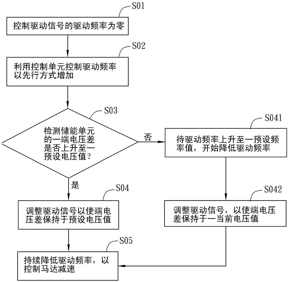
The invention discloses a motor reducing method and a motor driving device using the reducing method. The motor driving device comprises an energy storage unit and a control unit and outputs a driving signal to control a motor. The control unit is used for controlling the driving frequency of the driving signal. The motor reducing method comprises the steps of controlling the driving frequency to be zero, utilizing the control unit to control the driving frequency to be increased in a linear mode, detecting whether the terminal voltage difference of the energy storage unit rises to a certain preset voltage value, adjusting the driving signal to enable the terminal voltage difference to be maintained at the preset voltage value if the terminal voltage difference of the energy storage unit rises to the certain preset voltage value, and continuing to reduce the driving frequency so as to control the motor to reduce speed.

Description

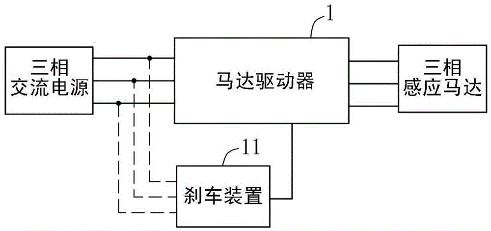
technical field [0001] The present invention relates to a motor deceleration method for decelerating a motor by controlling the driving frequency output to the motor and a motor drive device using the deceleration method. Background technique [0002] Please refer to figure 1 As shown in FIG. 1 , it is a driving schematic diagram of an existing three-phase AC induction motor. The driving system of the three-phase AC induction motor includes a three-phase AC power supply, a motor driver 1 and a three-phase induction motor. Wherein, the motor driver 1 can use pulse width modulation (PWM) technology to control the amplitude and frequency of the driving signal output by its converter, so as to control the rotation speed of the motor. When the output frequency of the drive signal is increased, the motor can be accelerated, and when the output frequency of the drive signal is decreased, the motor can be decelerated. [0003] In addition, in order to assist the conversion of ene...

Claims


Application Information

Patent Timeline
Patent Type & Authority Patents(China)
IPC IPC(8): H02P3/24
Inventor 纪建宇郭呈祥张胜捷谢庭钟廖世杰
Owner DELTA ELECTRONICS INC
Learn More