

Data transmission method and router
A data transmission and router technology, applied in the field of communication, can solve the problem of long network service interruption time, and achieve the effect of short service interruption time
- Summary
- Abstract
- Description
- Claims
- Application Information
AI Technical Summary
Problems solved by technology
Method used
Image

Examples
Embodiment 1
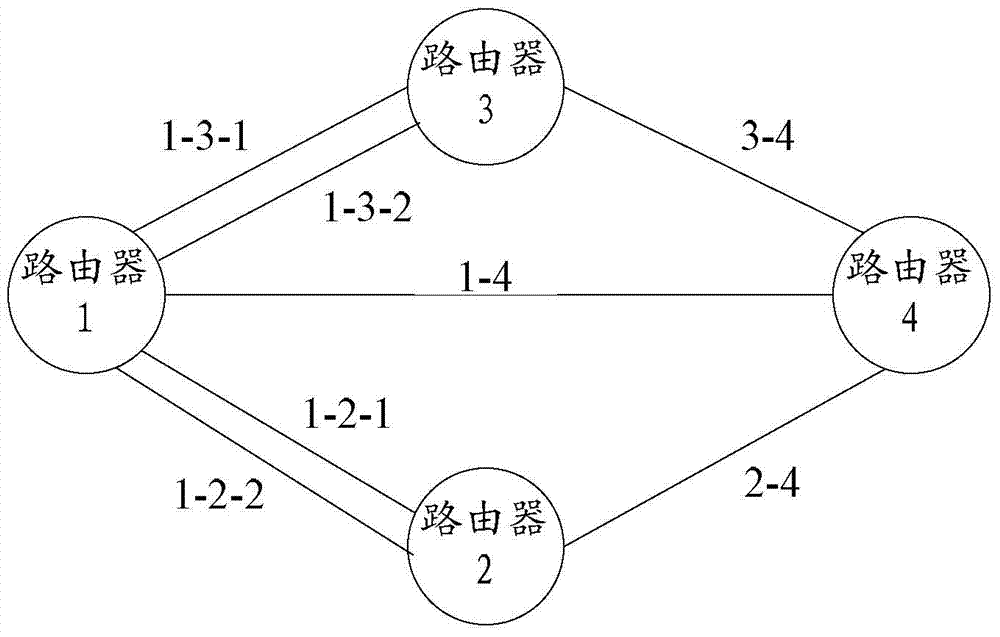
[0088] figure 2 It is a schematic diagram of a specific network node. Among them, there are two links 1-3-1 and 1-3-2 between Router 1 and Router 3, one link 1-4 between Router 1 and Router 4, and one link 1-4 between Router 1 and Router 2. There are 2 links 1-2-1 and 1-2-2, there is a link 3-4 between router 3 and router 4, and there is a link 2-4 between router 2 and router 4. And assume Router 1 receives the traffic.
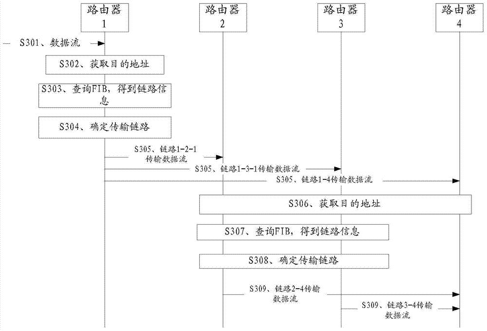
[0089] combine image 3 , the method provided in this embodiment specifically includes the following steps:
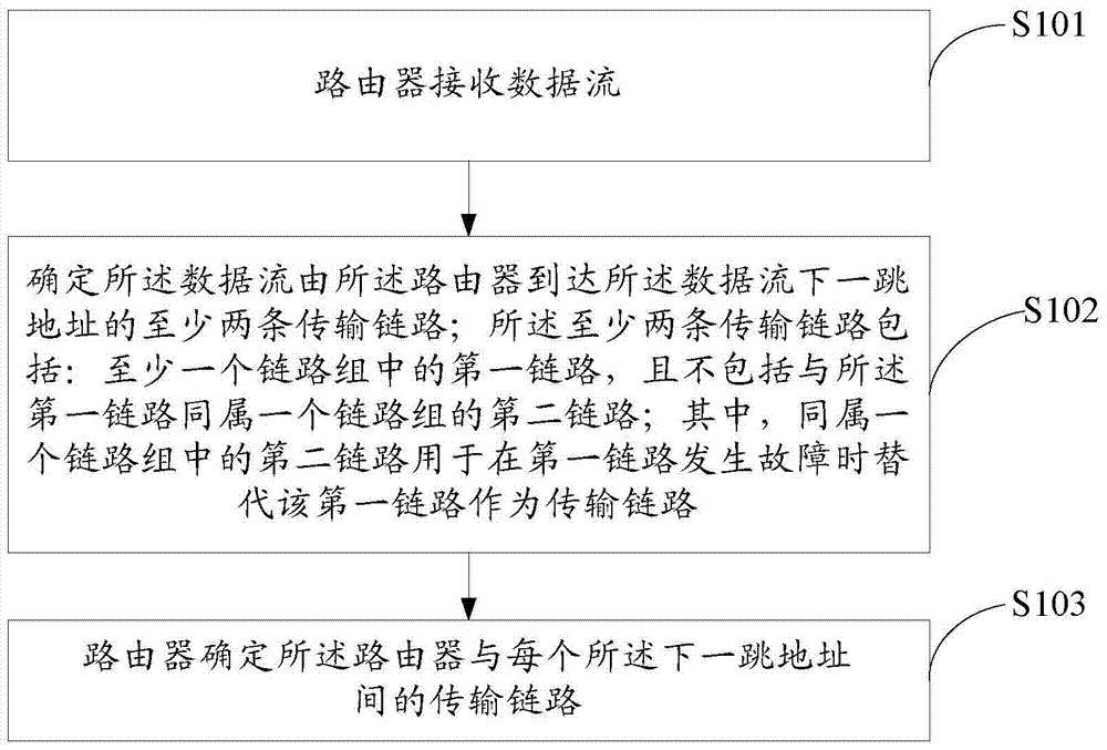
[0090] S301. Router 1 receives a data stream.
[0091] S302. Router 1 obtains the destination address of the data flow.
[0092] For example, router 1 may learn from the data flow that the destination address of the data flow is the address of router 4 .
[0093] S303. Router 1 queries the FIB in router 1 to obtain link information for the data flow from the router to the next-hop address of the data flow.
[0094] Referring to Table 1, in the...
Embodiment 2
[0132] Assume that in the first embodiment above, when router 1 is executing step S305, the first link in a link group fails, that is, the link fails when the data flow has not been sent. At this time, the method provided by the embodiment of the present invention further includes the following steps:
[0133] switching the first link to a second link. Wherein, the second link and the first link belong to the same link group.
[0134] After that, router 1 can use the three transmission links obtained after switching to continue to perform subsequent data stream transmission according to the data stream transmission mode in Embodiment 1.
[0135] For example, assume that link 1-2-1 fails when router 1 executes step S305, then at this time, router 1 may switch link 1-2-1 to link 1-2-2. Afterwards, router 1 uses the three transmission links obtained after switching (link 1-3-1, link 1-4, link 1-2-2) to continue to carry out data stream transmission in accordance with the first ...
Embodiment 3
[0139] Figure 4 Shown is a schematic diagram of a specific network node. Figure 4 and figure 2 The difference is that in Figure 4 In the example, there are four links 1-3-1, 1-3-2, 1-3-3, and 1-3-4 between router 1 and router 3.
[0140] combine Figure 5 , the method provided in this embodiment includes steps S501-S509, wherein, steps S501-S502 are the same as steps S301-S302 in the first embodiment, steps S508-S509 are the same as steps S308-S309 in the first embodiment, and are not repeated here repeat. In this embodiment, only the steps that are different from those in Embodiment 1 are listed. Specifically, steps S503-S507 may be:
[0141] S503. Router 1 queries the FIB in router 1 to obtain link information for the data flow from the router to the next-hop address of the data flow.
[0142] In this embodiment, the FIB table in router 1 includes the destination address, the link information corresponding to the destination address, and the link indication identif...
PUM
 Abstract
Description
Claims
Application Information