Terminal, network device and network system access method

A network device and network system technology, applied in access restriction, network traffic/resource management, connection management, etc., can solve problems such as insufficient utilization of network resources, low user data rate, etc., and reduce the risk of handover failure , Increase the peak data rate, increase the effect of user data rate

Active Publication Date: 2017-04-26
HUAWEI TECH CO LTD
View PDF5 Cites 0 Cited by
  • Summary
  • Abstract
  • Description
  • Claims
  • Application Information

AI Technical Summary

Problems solved by technology

[0004] In the prior art, under the intercommunication framework of packet data services between the LTE network and the CDMA HRPD network, although a terminal (User Equipment, UE) can switch between the two networks, the terminal can only switch between the two networks at the same time. Data services are performed in the system (LTE or CDMA HRPD), the network resources cannot be fully utilized, and the user's data rate is low

Method used


Image

  • Terminal, network device and network system access method
  • Terminal, network device and network system access method
  • Terminal, network device and network system access method

Examples


specific Embodiment approach

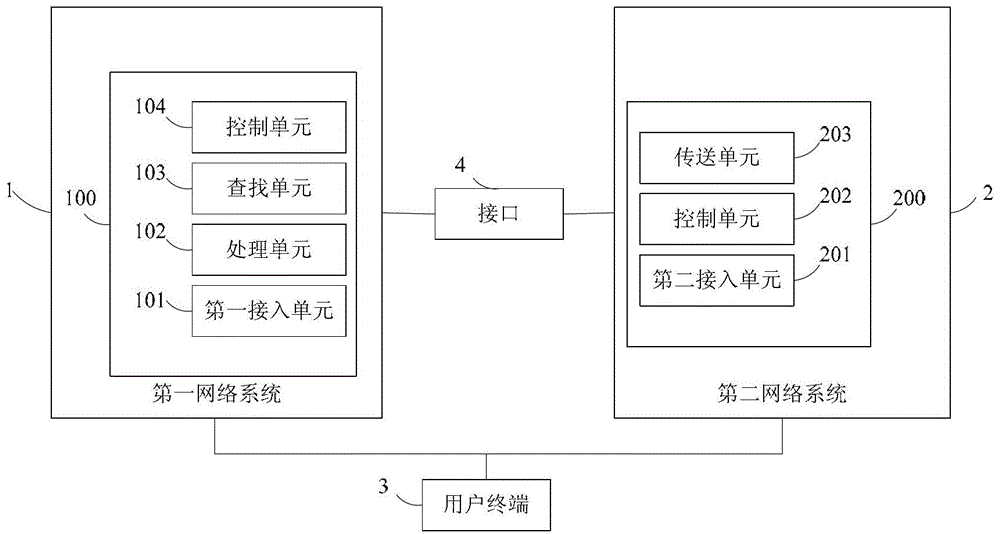
[0101] As another specific implementation manner, the second network device 200 includes:

[0102] The first sending / receiving unit is configured to receive a bearer establishment request from the first network device, where the bearer establishment request includes relevant information of terminals in the first network system;

[0103] A control unit, configured to establish a connection with the terminal according to the relevant information of the terminal, and create a radio bearer for carrying services of the terminal according to the bearer establishment request.

[0104] The second sending / receiving unit is used for transmitting information with the terminal.

[0105] The first sending and receiving unit is also used to forward the downlink data sent by the first network device 100 to the terminal 3 (the data is service data carried by the second network system 2), and the terminal 3 sends to the first network device 100 The uplink data (the data is the service data ca...

Embodiment approach

[0179] The present invention also provides another specific implementation manner of a carrier aggregation method, such as Figure 10 As shown, the method includes the following steps:

[0180] C1. The user establishes a connection in the LTE network system through the eNB (the eNB establishes an RRC connection with the terminal), and performs data services.

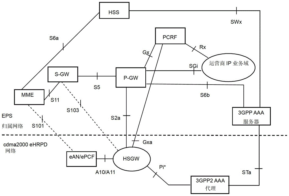
[0181] C2. The eNB selects the target carrier to participate in the aggregation according to the carrier measurement results of the eHRPD network system reported by the terminal, such as the carrier with the strongest signal in the measurement report as the target carrier, and determines the corresponding eHRPD according to the carrier frequency and pilot offset eAN / ePCF of the network. The eNB allocates the services carried by the LTE network system and the eHRPD network system, determines the mapping relationship between the allocated services and the bearers, and converts the Qos parameters (converting the LTE QoS pa...


PUM


Abstract

The invention discloses a method for accessing a network system, which is characterized by comprising the following steps: a first network device of a first network system receives a measurement about a second network system sent by a terminal of the first network system report; the first network device determines the second network device in the second network system according to the measurement report; the first network device sends a bearer establishment request to the second network device, so that the second The network equipment establishes a connection with the terminal; meanwhile, the present invention also provides a specific structure of the network equipment and the terminal. The present invention realizes the aggregation between the two network systems, and can dynamically schedule the resources of the two network systems according to the loads of the two network systems, thereby providing very efficient load balancing, and can effectively and significantly increase the peak data rate of users.

Description

technical field [0001] The present invention relates to the technical field of wireless communication, in particular to a terminal, network equipment and a network system access method. Background technique [0002] In order to meet the challenge of the wireless broadband technology and maintain the leading edge of the 3rd Generation Partnership Project (The 3rd Generation Partnership Project, 3GPP) network, the 3GPP formulated a long-term evolution plan (LongTerm Evolution, LTE) at the end of 2004. Under the guidance of this evolution plan, a new mobile communication network architecture is defined. This architecture only retains the packet switching (Packet Switched, PS) domain. Therefore, this architecture is called the Evolved Packet System (the corresponding English full name is Evolved Packet System , EPS or System Architecture Evolution, SAE). The architecture of the LTE system is as follows figure 1 As shown, among them, the GPRS service support node SGSN (Serving ...

Claims


Application Information

Patent Timeline
Patent Type & Authority Patents(China)
IPC IPC(8): H04W28/08H04W76/02
CPCH04W48/18H04W76/16H04W36/30H04W28/0865H04W36/0072H04W88/08H04W36/36
Inventor 刘继兴郭轶扈曙辉
Owner HUAWEI TECH CO LTD
Why Eureka
Try Eureka