Inward-pushing-type clamping device of three-dimensional corner clamping tube in numerically-controlled tube bending machine

A three-dimensional, clamping device technology, applied in the field of push-in clamping devices, can solve the problems of performance degradation at damaged parts, easy loosening of bent pipes, abnormal deformation, etc., achieve high processing accuracy and avoid uneven movement Effect

Active Publication Date: 2014-02-19
ANHUI DEXI DHI TECH
View PDF7 Cites 18 Cited by
  • Summary
  • Abstract
  • Description
  • Claims
  • Application Information

AI Technical Summary

Problems solved by technology

[0009] In the operation of the existing clamping device, when the clamping is not tight, the elbow is easy to loosen, and the pipe and the clamping device are prone to serious sliding phenomenon, accompanied by damage to the appearance of the pipe, while the clamping is too tight. Damage to the pipe and produce abnormal deformation, and the clamping device itself cannot rotate, resulting in the bent pipe not being absolutely streamlined at the bend, the appearance of the processed bend is not in harmony with the overall car, and the performance of the damage is reduced. The problem of short service life caused by easy corrosion, the present invention provides a three-dimensional three-dimensional corner clamping clamping device in the numerical control pipe bending machine, which can clamp the pipe well and avoid slippage when bending the pipe Phenomenon and damage to the appearance of the pipe

Method used


Image

  • Inward-pushing-type clamping device of three-dimensional corner clamping tube in numerically-controlled tube bending machine
  • Inward-pushing-type clamping device of three-dimensional corner clamping tube in numerically-controlled tube bending machine

Examples


Embodiment 1

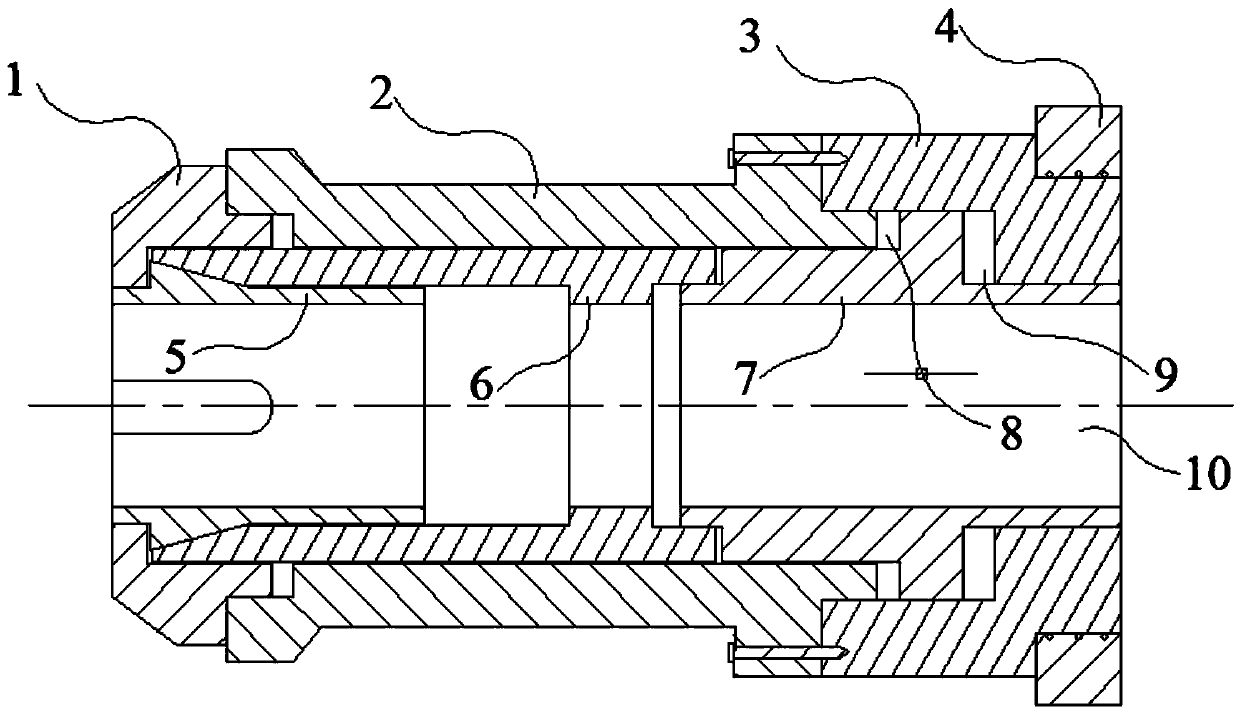
[0034] Such as figure 1 As shown, an internal push clamping device for a three-dimensional three-dimensional corner clamping pipe in a CNC pipe bender includes an elastic chuck 5, and also includes a top fixing sleeve 1, an outer fixing sleeve 2, a hydraulic outer cylinder 3, a bearing 4, The inner pushing sleeve 6, the hydraulic inner cylinder 7, the first hydraulic chamber 8 and the second hydraulic chamber 9, the top fixing sleeve 1, the outer fixing sleeve 2, the hydraulic outer cylinder 3, the bearing 4, the elastic chuck 5, the inner pushing The sleeve 6, the hydraulic inner cylinder 7, the first hydraulic chamber 8 and the second hydraulic chamber 9 are all rotationally symmetrical structures, have a common central axis, and jointly form a clamping cavity 10 inside;

[0035] The shape of the elastic chuck 5 is a circular tube with a ring of protrusions on the outside. The protrusions are composed of two sides, the left side and the right side. The left side is perpendicula...


PUM


Abstract

The invention discloses an inward-pushing-type clamping device of a three-dimensional corner clamping tube in a numerically-controlled tube bending machine, and belongs to the field of numerically-controlled tube bending machines. The inward-pushing-type clamping device comprises a flexible chuck, and further comprises a top end fixing sleeve, an outer fixing sleeve, a hydraulic outer cylinder, a bearing, an inward-pushing sleeve, a hydraulic inner cylinder, a first hydraulic cavity and a second hydraulic cavity. The top end fixing sleeve, the outer fixing sleeve, the hydraulic outer cylinder, the bearing, the flexible chuck, the inward-pushing sleeve, the hydraulic inner cylinder, the first hydraulic cavity and the second hydraulic cavity are respectively of a rotationally-symmetric structure, share the same central axis and internally forms a clamping inner cavity jointly. Due to the arrangement and assembling relationship of the components, when the inward-pushing-type clamping device clamps tubes, clamping force is easily controlled, tubes are not damaged, it is ensured that the inward pushing sleeve is steadily pushed to move and the flexible chuck is steadily pushed to contract in the clamping process, and the damage and skid, caused by uneven moving, of a workpiece are avoided.

Description

Technical field [0001] The invention belongs to the field of numerically controlled pipe benders, and specifically relates to an internal push-type clamping device of a three-dimensional corner clamping pipe in a numerically controlled pipe bender. Background technique [0002] Pipe bending machines can be roughly divided into CNC pipe bending machines, hydraulic pipe bending machines and so on. The hydraulic pipe bender is mainly used for laying and repairing pipelines in electric power construction, highway and railway construction, boilers, bridges, ships, furniture, decoration, etc. It has the advantages of multiple functions, reasonable structure, simple operation, convenient movement, and fast installation. Numerical control pipe bending machine, which can perform winding bending with one bending radius (single mode) or two bending radii (dual mode) for pipes in cold state. It is widely used in the bending of various pipe fittings and wires in industries such as automobiles...

Claims


Application Information

Patent Timeline
Patent Type & Authority Applications(China)
IPC IPC(8): B21D7/16
Inventor 吴善普吴善照
Owner ANHUI DEXI DHI TECH
Why Eureka
Try Eureka