Floating supporting mechanism

A floating support and support rod technology, which is applied in the field of workpiece processing, can solve the problems of difficult clamping and achieve the effects of reducing clamping difficulty, reducing vibration, and improving machining accuracy and smoothness

Active Publication Date: 2014-02-19
ANHUI PROVINCE JIEYONGDA INTELLIGENT MACHINE
View PDF7 Cites 3 Cited by
  • Summary
  • Abstract
  • Description
  • Claims
  • Application Information

AI Technical Summary

Problems solved by technology

In the prior art, the support mechanism is usually used by the operator to select a pad with a certain thickness based on experience. This method relies on the operator's experience and makes clamping difficult.

Method used


Image

  • Floating supporting mechanism
  • Floating supporting mechanism

Examples


Embodiment Construction

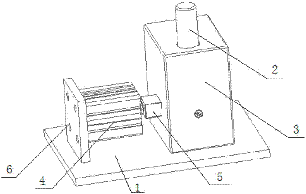
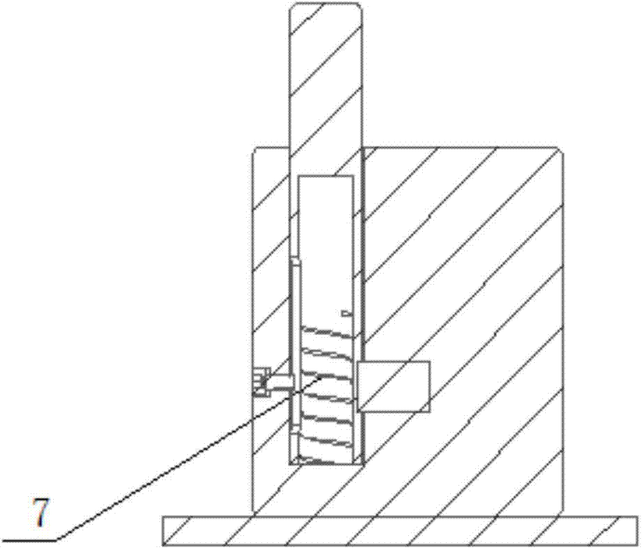
[0014] Such as figure 1 , figure 2 as shown, figure 1 It is a structural schematic diagram of a floating support mechanism proposed by the present invention; figure 2 It is a schematic cross-sectional view of a floating support mechanism proposed by the present invention.

[0015] refer to figure 1 , figure 2 , a floating support mechanism proposed by the present invention, comprising: a base 1, a driving device 4, a support rod 2, a box body 3, a locking device 5 and an elastic element 7, wherein:

[0016] The driving device 4 and the box body 3 are installed on the base 1, and an installation groove is vertically arranged in the box body 3, and the top of the installation groove communicates with the outside, and the support rod 2 and the elastic element 7 are installed in the installation groove, wherein the elastic element 7 is located in Below the support rod 2, the upper part of the support rod 2 protrudes from the outside of the box body 3, and the support surfa...


PUM


Abstract

The invention discloses a floating supporting mechanism. The floating supporting mechanism comprises a base, a driving device, a supporting rod, a box body, a locking device and an elastic component, wherein the driving device and the box body are installed on the base, a mounting groove is vertically formed in the box body, the upper portion of the mounting groove is communicated with the outside, the supporting rod and the elastic component are installed in the mounting groove, the elastic component is located below the supporting rod, the upper portion of the supporting rod stretches out of the box body, and the supporting face at the top end of the supporting rod is a horizontal plane; a channel groove is formed in the horizontal position, corresponding to the locking device, of the box body, the horizontal position of the channel groove is lower than the side face of the supporting rod, and the driving device is in driving connection with the locking device and drives the locking device to act, so that the locking device enters the box body through the channel groove to lock the supporting rod.

Description

technical field [0001] The invention relates to the technical field of workpiece processing, in particular to a floating support mechanism. Background technique [0002] In the process of workpiece processing, due to the difference in height of blank parts, it is difficult for the fixed fixture support mechanism to adapt to the difference of parts, resulting in high processing difficulty and low processing accuracy. Therefore, in the process of workpiece processing, a support mechanism is required to support blank parts with different heights. The support mechanism can automatically adapt to the difference of the parts to achieve the purpose of top tightening or support. In the prior art, the support mechanism is usually acted by the operator selecting pads with a certain thickness based on experience. This method depends on the experience of the operator and makes clamping difficult. Contents of the invention [0003] In order to solve the technical problems in the back...

Claims


Application Information

Patent Timeline
Patent Type & Authority Applications(China)
IPC IPC(8): B23Q3/00
CPCB23Q1/25B23Q3/00
Inventor 郑新生李敏罗勇刚
Owner ANHUI PROVINCE JIEYONGDA INTELLIGENT MACHINE
Why Eureka
Try Eureka