Multifunctional clamping fork

A multi-functional, fork body technology, applied in the direction of lifting device, earth mover/excavator, construction, etc., to achieve the effect of convenient placement

Active Publication Date: 2014-02-19
GUANGXI LIUGONG MASCH CO LTD
View PDF4 Cites 6 Cited by
  • Summary
  • Abstract
  • Description
  • Claims
  • Application Information

AI Technical Summary

Problems solved by technology

[0003] The purpose of the present invention is to provide a multi-functional fork that can hold various materials with different radial dimensions in view of

Method used


Image

  • Multifunctional clamping fork
  • Multifunctional clamping fork
  • Multifunctional clamping fork

Examples


Example Embodiment

[0028] The specific implementation scheme is described below in conjunction with the drawings.

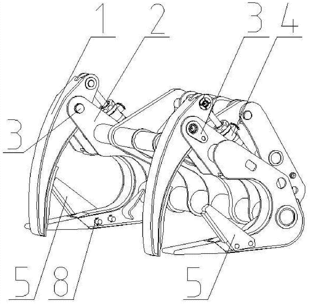
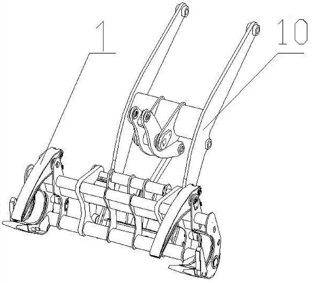
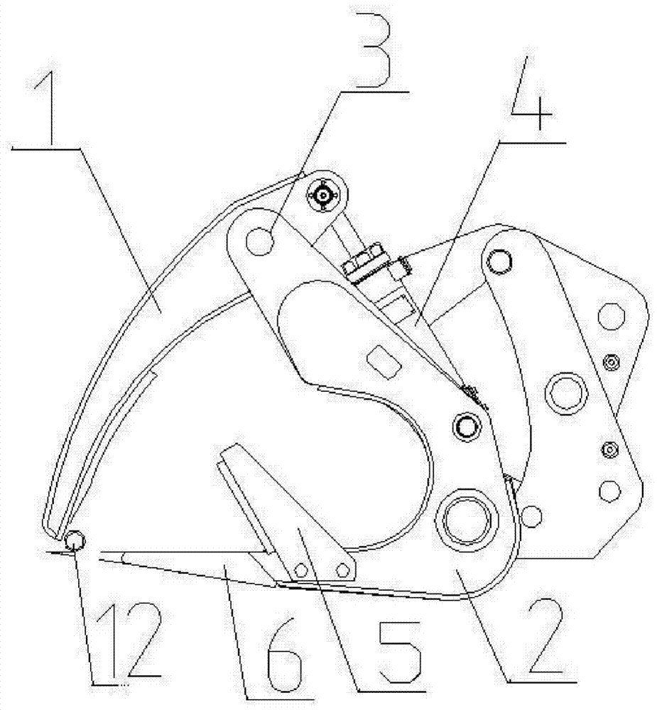
[0029] Such as figure 1 As shown, the holding fork in this embodiment includes two lower fork bodies 2 and an upper fork body 1. Each lower fork body 2 is roughly in a U-shaped structure, and the two lower fork bodies 2 are connected by a round steel tube or other mechanism. A left-right symmetrical structure is formed, and the upper fork body 1 is correspondingly hinged on the top of the lower fork body 2 through a pin 3. The rear end of the upper fork body 1 is connected with a hydraulic cylinder 4 and is driven by the hydraulic cylinder 4 to rotate around the pin shaft 3. An auxiliary fork body 5 is provided in the middle of the lower fork body tines 6. The entire fork can be connected with the boom 10 of the loader, such as figure 2 Shown.

[0030] Such as Figure 5 to Figure 7 As shown, the auxiliary fork body 5 is composed of a clamping portion 7 and a plug-in connecting porti...


PUM


Abstract

The invention relates to a multifunctional clamping fork so as to solve the problem that a clamping fork corresponding to materials in size needs to be arranged when the existing clamping fork is used for clamping a plurality of materials large in transverse size disparity. The multifunctional clamping fork comprises a lower fork body of a rough transversely-arranged-U shape, and an upper fork body connected to the top of the lower fork body in a rotating mode through a hinge pin. The rear end of the upper fork body is connected with a hydraulic oil cylinder. A fork tooth of the lower fork body is provided with a detachable pointing upper fork body and an auxiliary fork body which can not rotate relative to the lower fork body. According to the multifunctional clamping fork, the auxiliary fork body is disassembled and removed, the multifunctional clamping fork still can clamp a pipe or a cylinder larger in size as the traditional clamping fork, the auxiliary fork body is installed on the lower fork body and form a branch fork on the lower fork body, slender objects are clamped into the branch fork formed by the lower fork body tooth front portion and the auxiliary fork body through the upper fork body, and can be well fixed, and therefore the multifunctional clamping fork can clamp, assemble and disassemble the materials large in transverse size disparity, and is multipurpose.

Description

technical field [0001] The invention relates to a holding fork, in particular to a multifunctional holding fork. Background technique [0002] The fork is one of the more commonly used attachments used by loaders. It is used in forestry, paper industry, petroleum industry, steel industry, construction industry, transportation and other important fields for clamping, stacking and placing materials. The fork usually includes an upper fork body and a lower fork body. The lower fork body is roughly in the shape of a horizontal U. The top of the lower fork body is connected to the upper fork body through a pin shaft. Driven by the oil cylinder, the upper fork body rotates around the pin shaft, and the front part of the upper fork body and the rear part of the lower fork body form a clamping part to clamp the material to be clamped between the upper fork body and the lower fork body. The existing structure and functions of the holding fork are difficult to meet the needs of the c...

Claims


Application Information

Patent Timeline
IPC IPC(8): E02F3/413B66F9/18
Inventor 区思榜黄意业黄家胜杨雪芹蒋正忠蒋小林姬鹏举覃忠添
Owner GUANGXI LIUGONG MASCH CO LTD
Why Eureka
Try Eureka