Check vavle

A technology of check valves and valve components, which is applied in the direction of lift valves, valve details, control valves, etc., and can solve problems such as low height of oil column

Active Publication Date: 2014-02-19
POLYTEC PLASTICS GERMANY
View PDF8 Cites 7 Cited by
  • Summary
  • Abstract
  • Description
  • Claims
  • Application Information

AI Technical Summary

Problems solved by technology

This has the disadvantage that the oil column necessary to open the check valve has an extremely low height, making it possible to cause problems in oil return flow
He...

Method used


Image

  • Check vavle
  • Check vavle
  • Check vavle

Examples


Embodiment Construction

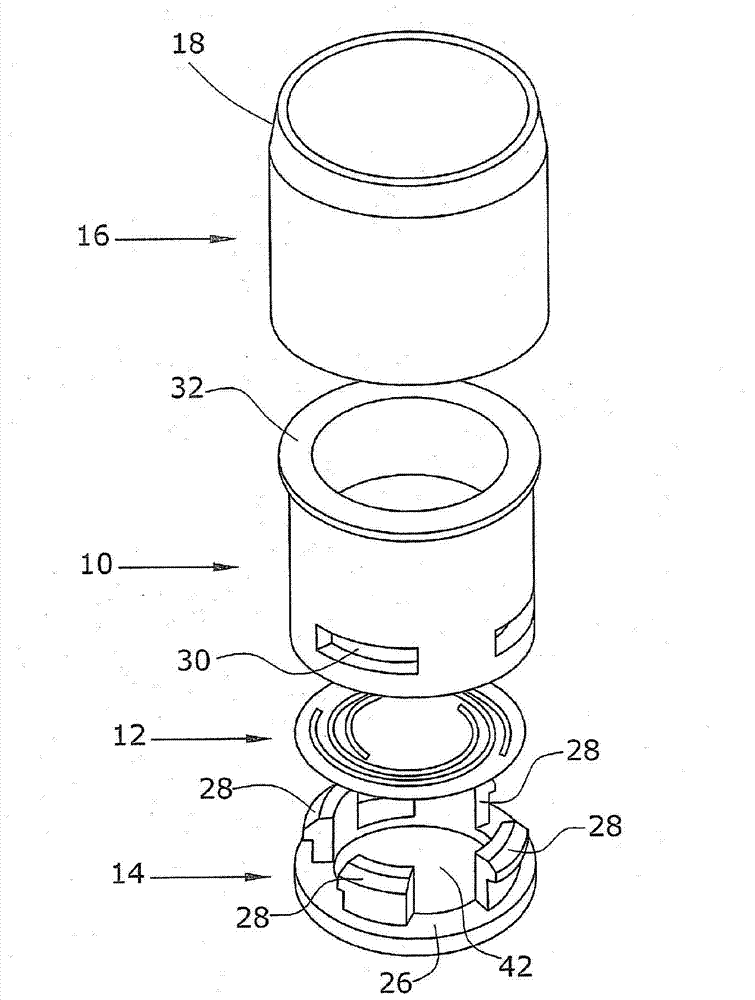
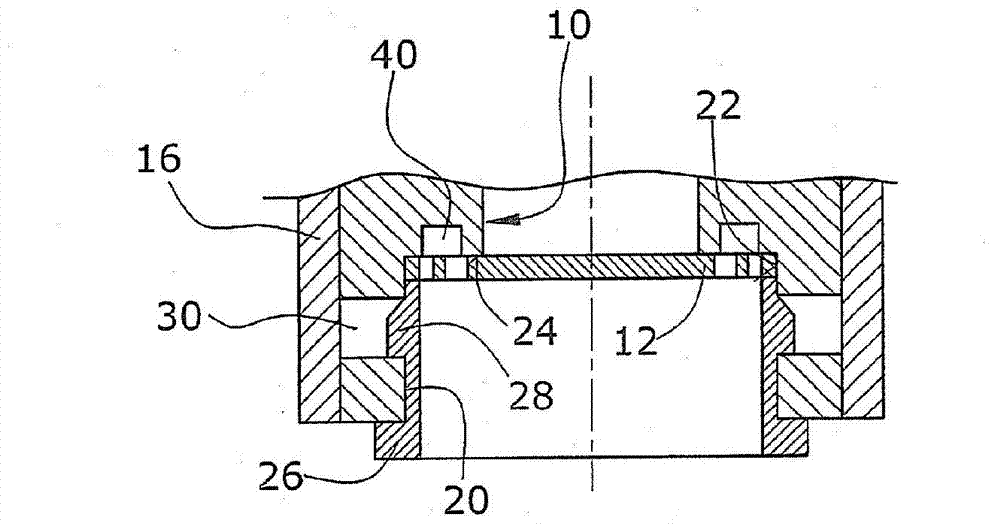
[0022] In the first preferred implementation form ( figure 1 and 2 ), the non-return valve has a plastic housing 10 in which a valve element 12 is arranged and fixed by means of a retaining element 14 . In the preferred embodiment, the housing 10 is surrounded by a metal sleeve 16 . In particular, the metal sleeve 16 can be inserted into an opening in the crankcase with an interference fit. The sleeve 16 has a section 18 in order to simply press the sleeve 16 into the opening with an interference fit.

[0023] In a first assembly step, the valve element 12 is figure 1 Inserted from below into the substantially cylindrical housing and fixed by means of fastening elements 14 .

[0024] In order to ensure a secure fixation of the valve element 12 , in the exemplary embodiment shown the housing 10 has a cylindrical opening 20 through which the valve element 12 is inserted. Furthermore, the housing 10 has a platform and a constriction whose diameter is reduced to a cylindrical...


PUM


Abstract

The invention relates to a check valve which is particularly suitable for being arranged in an oil backflow channel. The oil backflow channel is arranged between a crankcase and an oil chamber of an oil pan, and the check valve is provided with a casing (10). The inside of the casing (10) is provided with a plate-shaped stamped valve element (12). The valve element (12) is fixed via a holding element (14) connected with the casing particularly through locking element pairs (28, 30). The plastic casing is surrounded by a metal sleeve (16) preferably, and the metal sleeve can be pressed into the opening of the crankcase in an interference mode.

Description

technical field [0001] The invention relates to a non-return valve which is particularly suitable for use in motor vehicles. The non-return valve is preferably designed to be arranged in a return channel which leads from the motor component to an oil reservoir, such as an oil sump. Background technique [0002] In order to discharge the oil or oil mist present in the crankcase, an oil separation takes place in the crankcase by means of an oil separator. The separated oil is led back into the oil reservoir, in particular into the oil sump. Evacuation of secondary air must be avoided here. For this purpose, it is known to provide non-return valves. Usually, the non-return valve is integrated directly into the oil separator or into the cylinder head cover. This has the disadvantage that the oil column necessary to open the non-return valve has an extremely low height, which can cause problems in oil return flow. This leads to an increased accumulation of oil in the oil sep...

Claims


Application Information

Patent Timeline
IPC IPC(8): F16K15/00F01M13/04
CPCF01M13/04F01M2013/0494F16K1/36F16K15/031F16K27/0209
Inventor 海伦·埃斯德斯约格·苏亚雷斯汉斯·扬森
Owner POLYTEC PLASTICS GERMANY
Why Eureka
Try Eureka