

Bulb lamp structure
A technology of bulb lamps and lampshades, applied in lighting and heating equipment, semiconductor devices of light-emitting elements, point light sources, etc.
- Summary
- Abstract
- Description
- Claims
- Application Information
AI Technical Summary
Problems solved by technology
Method used
Image

Examples
no. 1 example
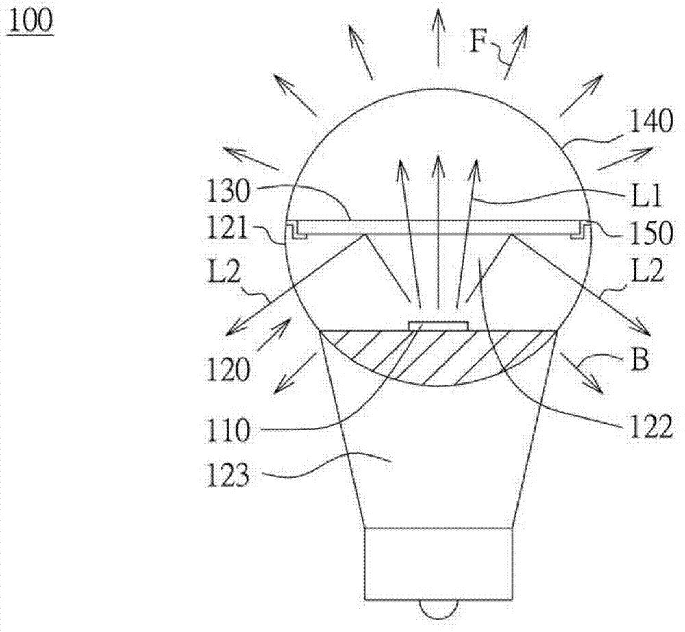
[0035] Please refer to figure 1 , which shows a schematic diagram of a bulb lamp structure 100 according to an embodiment of the present invention. The bulb structure 100 includes a light source 110 , a casing 120 , an optical film 130 and a lampshade 140 . The lampshade 140 is detachably assembled on the housing 120 and located right above the light source 110 . Preferably, but not limited, the lampshade 140 and the casing 120 are combined into a translucent sphere to accommodate the light source 110, and the lampshade 140 and the casing 120 are fastened around the opening 122 with a screw locking structure (not shown). ) are engaged with each other, so that the lampshade 140 can be fixed above the opening 122 . In addition, the casing 120 is further provided with an engaging structure 150 around the opening 122 , such as a hook or a groove, so that the optical film 130 is fixed on the casing 120 .
[0036] In one embodiment, the casing 120 has a lamp holder 123 for fixing...
no. 2 example
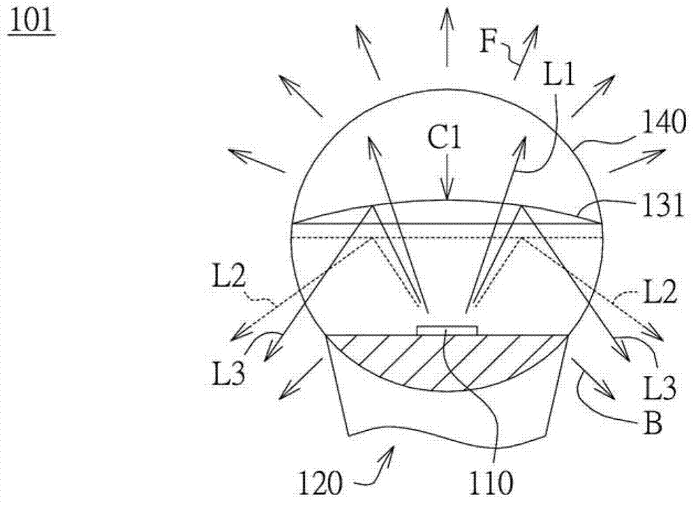
[0041] Please refer to figure 2 , which shows a schematic diagram of a bulb lamp structure 101 according to another embodiment of the present invention. The similarities between the second embodiment and the first embodiment will not be repeated, and the difference lies in that the optical film 131 has a curved surface C1 protruding toward the lampshade 140 . The curved surface C1 can change the light angle of the backlight B. exist figure 2 In the figure, the dotted line represents the light L2 emitted to the rear of the bulb lamp 100 in the first embodiment, and the solid line represents the light L3 emitted to the rear of the bulb lamp 101 in the second embodiment. It can be seen that through the optical The light emitting angle of the light L3 reflected by the diaphragm 131 is relatively large, for example, increased from 220 degrees to 240 degrees or larger, thereby changing the light emitting angle of the back light B. In addition, the light emitting angle of the fo...
no. 3 example
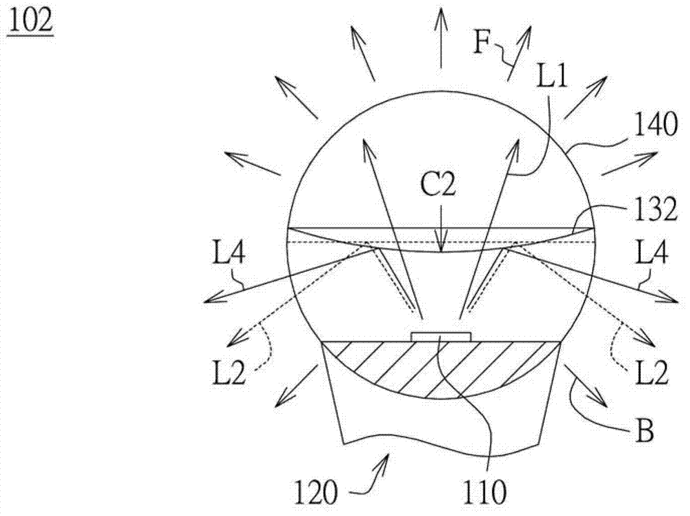
[0044] Please refer to image 3 , which shows a schematic diagram of a bulb lamp structure 102 according to another embodiment of the present invention. The similarities between the third embodiment and the first embodiment will not be repeated, and the difference lies in that the optical film 132 has a curved surface C2 protruding toward the light source 110 . The curved surface C2 can change the light angle of the backlight B. exist figure 2 In the figure, the dotted line represents the light L2 emitted to the rear of the bulb lamp 100 in the first embodiment, and the solid line represents the light L4 emitted to the rear of the bulb lamp 102 in the third embodiment. It can be seen that through the optical The light emitting angle of the light L4 reflected by the diaphragm 132 is smaller, for example, reduced from 220 degrees to 200 degrees or less, thereby changing the light emitting angle of the back light B. In addition, the light emitting angle of the forward light F...
PUM
 Abstract
Description
Claims
Application Information