light guide plate

A technology of light guide plate and substrate, applied in the field of light guide plate, which can solve the problems of vignetting, difference between the brightness and darkness of the picture, and the dark part of the light.

Active Publication Date: 2021-06-08
YANGXIN TECH SUZHOU
View PDF23 Cites 0 Cited by
  • Summary
  • Abstract
  • Description
  • Claims
  • Application Information

AI Technical Summary

Problems solved by technology

[0003] The microstructure on the light guide plate reduces the light-emitting angle of the light-emitting element through the principle of structural refraction, thereby improving the utilization ...

Method used


Image

  • light guide plate
  • light guide plate
  • light guide plate

Examples


Embodiment Construction

[0015] The aforementioned and other technical contents, features and effects of the present invention will be clearly presented in the following detailed description of a preferred embodiment with reference to the accompanying drawings. The directional terms mentioned in the following embodiments, such as: up, down, left, right, front or back, etc., are only referring to the directions of the drawings. Accordingly, the directional terms are used to illustrate and not to limit the invention.

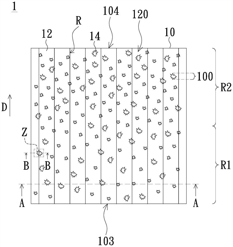
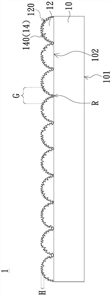
[0016] Please refer to figure 1 and figure 2 , figure 1 It is a schematic top view of a light guide plate according to an embodiment of the present invention. figure 2 for along figure 1 Schematic cross-sectional view of line AA shown. like figure 1 and figure 2 As shown, the light guide plate 1 of this example includes a substrate 10 , a plurality of lens microstructures 12 and a plurality of dot patterns 14 . The substrate 10 has a light emitting surface 101 , a bottom surfac...


PUM


Abstract

The invention discloses a light guide plate, which comprises a substrate, a plurality of lens microstructures and a plurality of dot patterns. The substrate has a light-emitting surface, a bottom surface opposite to the light-emitting surface, and a light-incident surface connected between the light-emitting surface and the bottom surface. These lens microstructures are arranged on the bottom surface of the substrate. These dot patterns are distributed on the lens microstructures, and part of the dot patterns are located at the junction of two adjacent lens microstructures. Under the structural design of the light guide plate of the present invention, the divergence angle of the light source can be effectively increased, the effect of light source scattering can be increased, and the problems of the difference between brightness and darkness of the picture, dark corners of the picture, and dark parts of light output can be improved.

Description

technical field [0001] The invention relates to a light guide plate, in particular to a light guide plate used for a light source module. Background technique [0002] In the side-illuminated light source module, the light guide plate is mainly used to guide the light beams emitted by the light-emitting elements (such as light-emitting diodes) disposed on the side of the light guide plate (that is, the light-incident surface) to the light guide plate. The front side of the light panel (that is, the light-emitting surface) to form a uniform surface light source. With the rapid development of light guide plate forming technology, some forming technologies applied to thin film materials are gradually applied in the forming of light guide plate. Forming microstructures on light guide plate to improve luminance and brightness is the most typical example. [0003] The microstructure on the light guide plate reduces the light-emitting angle of the light-emitting element through th...

Claims


Application Information

Patent Timeline
IPC IPC(8): G02B6/00
CPCG02B6/0043G02B5/021G02B6/0036G02B6/0038
Inventor 左利明邹庆钰
Owner YANGXIN TECH SUZHOU
Why Eureka
Try Eureka