Optical signal identification method applied to gate machine and gate machine

An identification method and optical signal technology, applied in the direction of instruments, close-range systems, single input port/output port register, etc. The problem of reducing the alignment range, etc., can reduce the difficulty of installation, expand the divergence angle, and increase the alignment margin.

Pending Publication Date: 2022-05-06
ZHEJIANG DAHUA TECH CO LTD
View PDF6 Cites 0 Cited by
  • Summary
  • Abstract
  • Description
  • Claims
  • Application Information

AI Technical Summary

Problems solved by technology

However, when the infrared module reduces the receiving and transmitting angle of the device, the alignment range is also reduced accordingly. The adjustable bracket cannot quantify the alignment margin between the emitter and the receiver during the installation process. Due to reasons such as cracking of the island base, settlement, thermal expansion and contraction of equipment, etc., the infrared points with the margin at the lower limit will be misaligned
[0004] Therefore, the existing technology cannot fully realize the alignment of the light emitter and the light receiver after the gate is installed

Method used


Image

  • Optical signal identification method applied to gate machine and gate machine
  • Optical signal identification method applied to gate machine and gate machine
  • Optical signal identification method applied to gate machine and gate machine

Examples


Embodiment Construction

[0027] The following will clearly and completely describe the technical solutions in the embodiments of the present application with reference to the accompanying drawings in the embodiments of the present application. Obviously, the described embodiments are only part of the embodiments of the present application, not all of them. Based on the embodiments in this application, all other embodiments obtained by persons of ordinary skill in the art without making creative efforts belong to the scope of protection of this application.

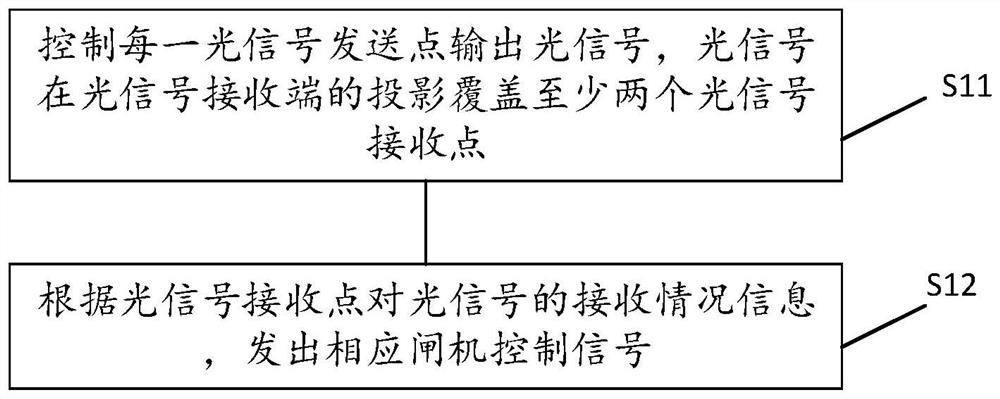
[0028] See figure 1 , is a schematic flowchart of the first embodiment of the method for identifying an optical signal applied to a gate according to the present invention, specifically including:

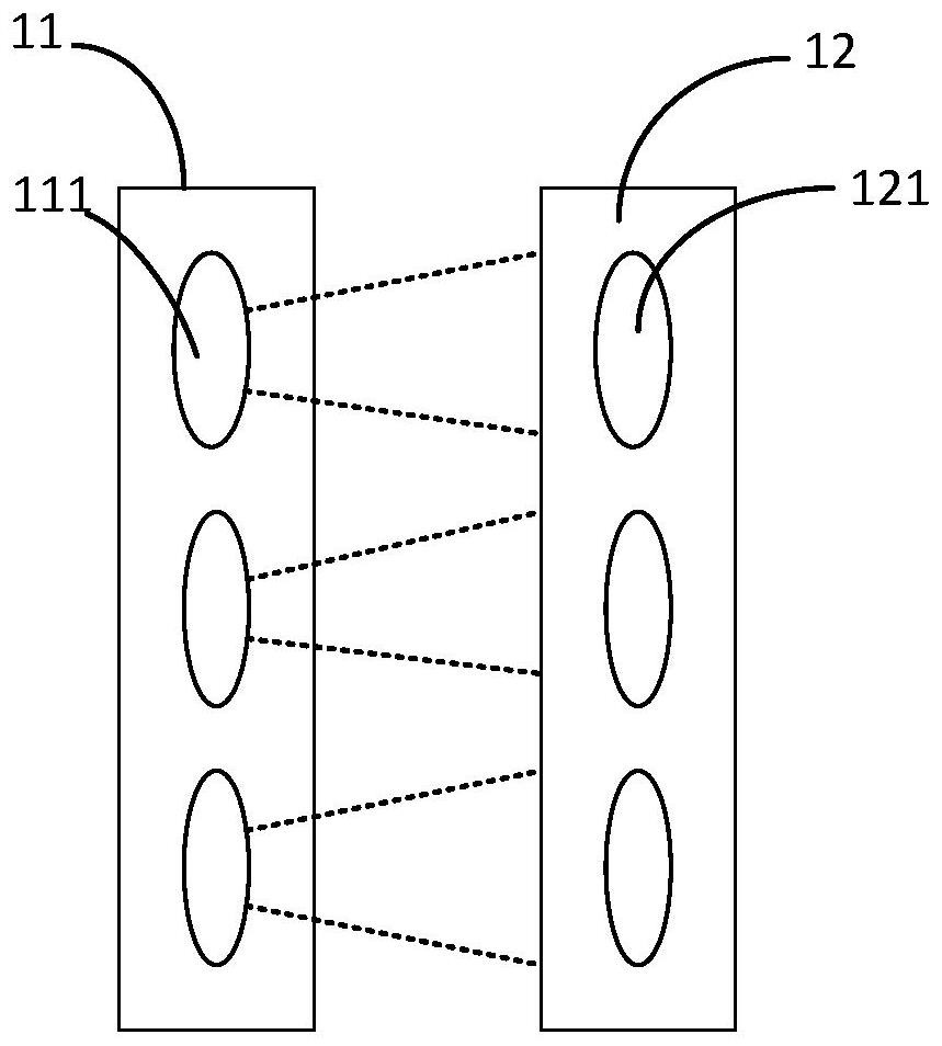
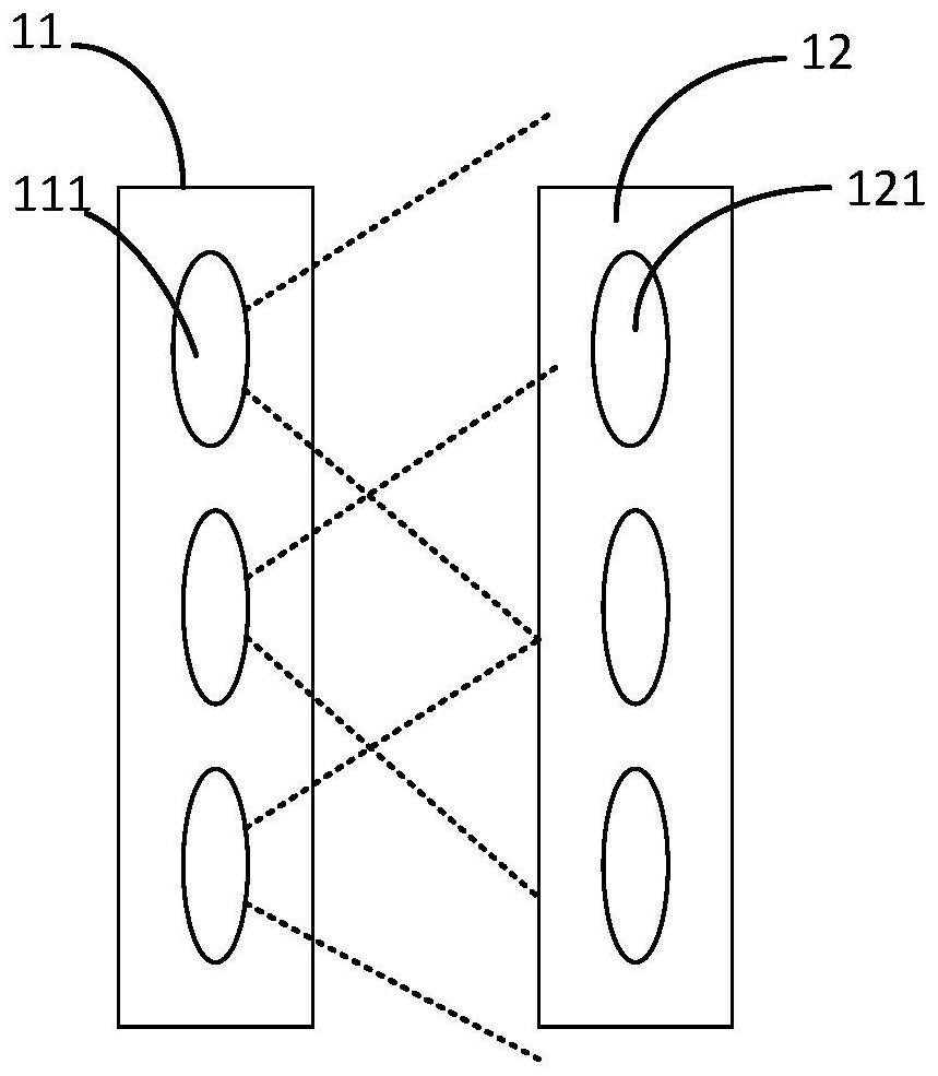
[0029] Step S11: controlling each of the optical signal sending points to output an optical signal, and the projection of the optical signal on the optical signal receiving end covers at least two of the optical signal receiving points.

[0030] Speci...


PUM


Abstract

The invention provides an optical signal identification method applied to a gate machine and the gate machine, the gate machine comprises an optical signal sending end and an optical signal receiving end, and the optical signal sending end comprises a plurality of optical signal sending points; the optical signal receiving end comprises a plurality of optical signal receiving points, and the optical signal sending points are in one-to-one correspondence with the optical signal receiving points; the optical signal identification method comprises the following steps: controlling each optical signal sending point to output an optical signal in a time-sharing manner, wherein the projection of the optical signal at the optical signal receiving end covers at least two optical signal receiving points; and the optical signal receiving point sends a corresponding gate control signal according to the receiving condition information of the optical signal by the optical signal receiving point. Therefore, on one hand, the alignment allowance between the light emitter and the light receiver of the gate can be increased, the installation difficulty is reduced, and on the other hand, crosstalk between the optical signals output by the adjacent optical signal sending points after the divergence angle is increased can be avoided.

Description

technical field [0001] The invention relates to the technical field of gates, in particular to an optical signal identification method applied to gates and the gates. Background technique [0002] The infrared modules commonly used in gates are real-time transmitting / receiving types. By arranging a certain number of infrared identification points on the longitudinal section of the gate channel to detect the passing behavior of passers-by, the opening and closing of doors, safety reminders and prevention doors are made according to the passing behavior. The strategy of wing collision or pinching passers-by, the density of infrared recognition points on the cut surface determines the recognition effect to a certain extent. In order to prevent mutual interference between identification points caused by the increase of infrared density, the common method is to reduce the transmitting and receiving angle between the infrared emitter and the light receiver. However, when the angl...

Claims


Application Information

Patent Timeline
Patent Type & Authority Applications(China)
IPC IPC(8): H04B10/114G07C9/00
CPCH04B10/114G07C9/00
Inventor 潘炜
Owner ZHEJIANG DAHUA TECH CO LTD
Why Eureka
Try Eureka