Simple calibration method of laser centering instrument

A technology of laser centering and calibration method, which is applied in the field of calibration, can solve the problems of unfavorable on-site maintenance and long calibration cycle after returning to the factory, and achieve the effects of shortening fault diagnosis time, convenient measurement and high accuracy

Active Publication Date: 2014-02-19
JIUQUAN IRON & STEEL GRP
View PDF3 Cites 20 Cited by
  • Summary
  • Abstract
  • Description
  • Claims
  • Application Information

AI Technical Summary

Problems solved by technology

However, the device can only be calibrated at its manufacturer (the manufacturers are all foreign companies), a

Method used


Image

  • Simple calibration method of laser centering instrument
  • Simple calibration method of laser centering instrument

Examples


Example Embodiment

[0020] The present invention will be further described in detail below in conjunction with specific embodiments and the accompanying drawings, but the embodiments of the present invention are not limited thereto.

[0021] The simple calibration method of the laser centering instrument provided by the present invention includes the simple calibration of the horizontal mechanical displacement centering indication value of the laser centering instrument and the vertical mechanical displacement centering indication value of the laser centering instrument.

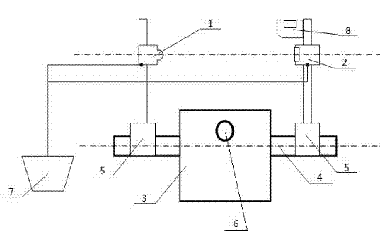
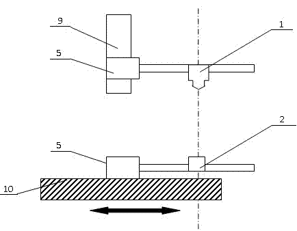
[0022] The minimum resolution of the laser alignment instrument is 0.01mm, and the minimum resolution of the angle is 1'. The supporting equipment of the laser alignment instrument includes: laser emitting disc 1, receiving target disc 2, V-shaped bracket 5, hand-operated display 7 and level 8.

[0023] The tailstock 3 of the universal length gauge is an integral part of the length gauge. The tailstock measuring mandrel 4 of the unive...


PUM


Abstract

The invention discloses a simple calibration method of a laser centering instrument, which comprises simple calibration for a horizontal mechanical displacement centering indication value and a vertical mechanical displacement centering indication value of the laser centering instrument. The simple calibration for the horizontal mechanical displacement centering indication value comprises the steps of installation of the laser centering instrument, zero position adjustment, 3-o' clock direction detection and 9-o' clock direction detection. The simple calibration for the vertical mechanical displacement centering indication value comprises the steps of installation of the laser centering instrument, zero position adjustment and detection for the actual displacement amount of vertical mechanical displacement. According to the simple calibration method disclosed by the invention, a simple standard device is combined by using a high-precision measurement core shaft and a universal tool microscope so as to carry out centering calibration for the laser centering instrument in the horizontal and vertical directions, and being convenient in measurement and high in accuracy. In practical production, self calibration can be carried out immediately when an abnormal value occurs when the laser centering instrument is in use, and outgoing calibration is not required, thereby shortening the time of fault diagnosis, and improving usage efficiency of the laser centering instrument.

Description

technical field [0001] The invention relates to a calibration method, in particular to a simple calibration method for a laser alignment instrument. Background technique [0002] All shafts, whether straight or curved, rotate about an axis called the center of rotation. The shape of the center of rotation is a straight line. When the respective centers of rotation of two axes form the same straight line, it is called concentric (collinear). When two shafts are not concentric, it is called misalignment. Mechanical displacement alignment refers to the center alignment of the connection parts when the couplings of mechanical equipment are connected to ensure the coaxiality of the installation of the couplings of the two equipments, so that the two equipments can avoid damage caused by vibration and jamming due to the deflection of the installation connection Equipment. The main function of the laser alignment instrument in the maintenance process of mechanical equipment is:...

Claims


Application Information

Patent Timeline
IPC IPC(8): G01B11/27
Inventor 齐磊钟贞
Owner JIUQUAN IRON & STEEL GRP
Why Eureka
Try Eureka