
Passive rectifying circuit

A technology of rectifier circuit and rectifier unit, which is applied in the direction of converting irreversible AC power input into DC power output, etc., can solve the problem of low support power level, and achieve the effect of high DC voltage level, strong boosting ability and low cost.

Inactive Publication Date: 2014-02-19
SHANGHAI JIAO TONG UNIV
View PDF3 Cites 0 Cited by
  • Summary
  • Abstract
  • Description
  • Claims
  • Application Information

AI Technical Summary

Problems solved by technology

At the same time, a DC-DC circuit is disclosed, which has a high boosting capability and requires three power sources: a DC voltage source, two pulse signals with phase shifts, and supports a lower power level.

Method used


Image

  • Passive rectifying circuit

Examples


Embodiment Construction

[0019] The present invention will be described in detail below in conjunction with specific embodiments. The following examples will help those skilled in the art to further understand the present invention, but do not limit the present invention in any form. It should be noted that those skilled in the art can make several modifications and improvements without departing from the concept of the present invention. These all belong to the protection scope of the present invention.

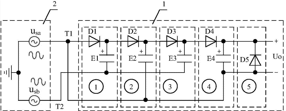
[0020] Such as figure 1 As shown, the passive rectification circuit provided by an embodiment of the present invention includes: an AC power supply 2 and a rectification circuit 1, and the AC power supply 2 includes a first voltage source and a second voltage source, both of which are common ground; The rectification circuit 1 is composed of four rectification units cascaded in sequence and one freewheeling unit; two-phase AC voltage is input to generate high-voltage DC voltage for supplying the s...


PUM


Abstract

The invention discloses a passive rectifying circuit in the technical field of power electronics. The passive rectifying circuit comprises an alternating current power source and a rectifying circuit body. The alternating current power source comprises a first voltage source and a second voltage source which are based on the same benchmark. The rectifying circuit body is composed of at least one rectifying unit and a flow current unit which are cascaded in sequence, and the two-phase alternating voltage is input to produce the high-voltage direct voltage to be used by a backward stage load. The passive rectifying circuit has the function of rectifying, the high-amplitude direct voltage can be produced, the more the number of series is, the higher the class of the direct voltage becomes, and the passive rectifying circuit has the advantages of being strong in boosting capacity, simple in structure, low in cost and the like.

Description

technical field [0001] The present invention relates to an AC-DC converter in the technical field of power electronics, in particular to a passive rectification circuit, that is, a rectification circuit capable of obtaining relatively high DC voltage output. Background technique [0002] With the development of power electronic conversion technology, there have been many DC power supply occasions that require high voltage DC voltage, such as laser power supply, ozone generator, plasma cutting machine arc starter, etc. [0003] Up to now, the composition of the boost circuit that supports higher power output generally includes the following two types: (1) active or passive schemes that use inductive devices and transformers to boost voltage; source or passive solution. The former has limited boosting capability, while the latter needs to consider the output voltage equalization of the converter. Each has advantages and disadvantages, but what they have in common is that the ...

Claims


Application Information

Patent Timeline
IPC IPC(8): H02M7/06
Inventor 渠浩杨喜军
Owner SHANGHAI JIAO TONG UNIV
Learn More