

LTE-A non-codebook beam forming method based on user satisfaction
A beamforming method and user satisfaction technology, applied in space transmit diversity, diversity/multi-antenna systems, etc., can solve the problem of low fairness satisfaction, achieve satisfaction and fairness, improve user fairness, The effect of improving system performance
- Summary
- Abstract
- Description
- Claims
- Application Information
AI Technical Summary
Problems solved by technology
Method used
Image

Examples
specific Embodiment approach 1
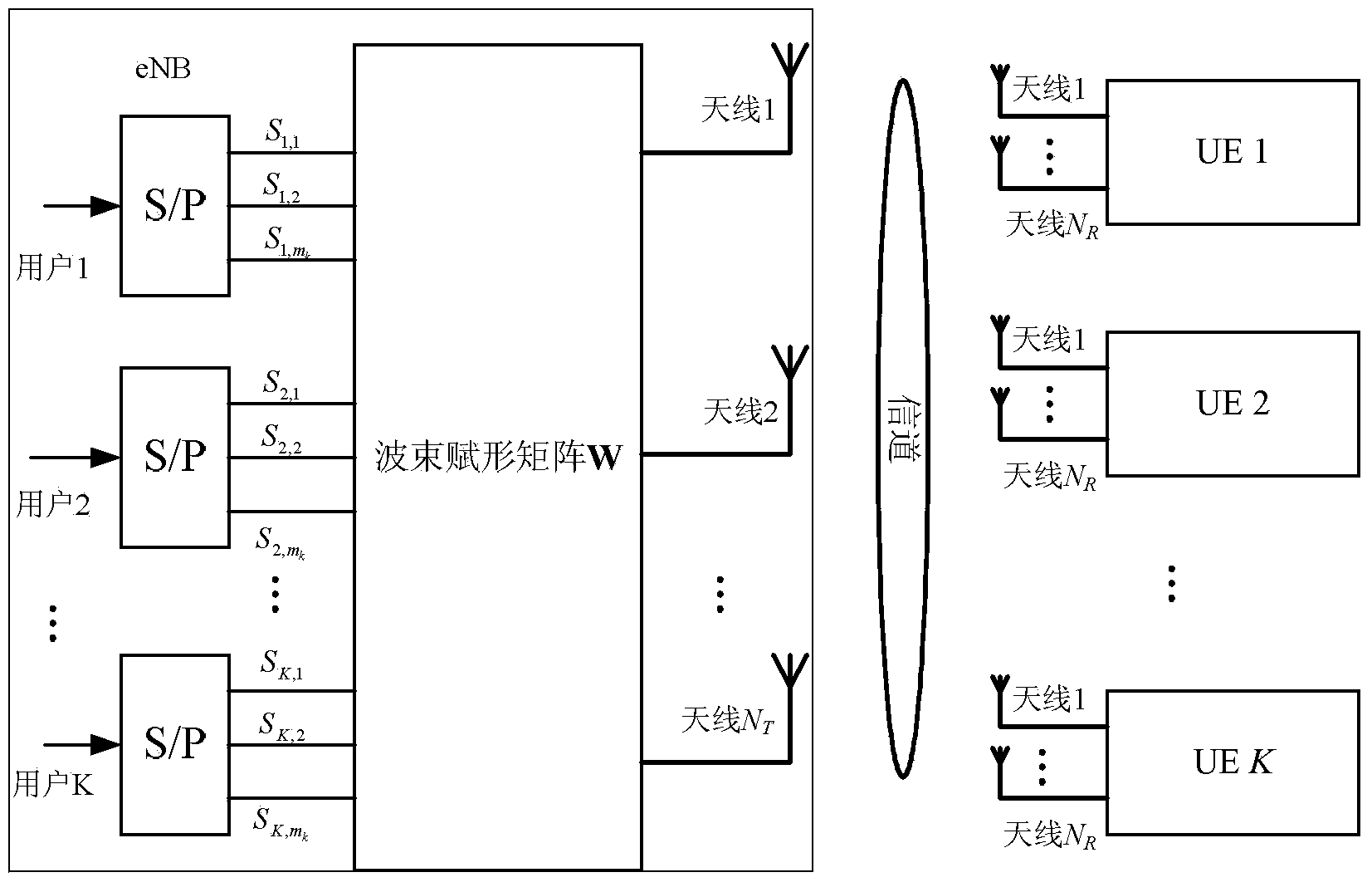
[0019] Specific implementation mode one: combine figure 1 Describe this embodiment, the LTE-A non-codebook beamforming method based on user satisfaction described in this embodiment, it comprises the following steps:
[0020] Step 1: Obtain the corresponding beamforming matrix by using the existing SLNR beamforming method;
[0021] Step 2: Under the beamforming matrix obtained in Step 1, obtain the SINR value and satisfaction value of each user;
[0022] Step 3: Using the obtained SINR value and satisfaction value, modify and weight the beamforming matrix obtained in step 1 to obtain the modified and weighted beamforming matrix;
[0023] Step 4: For the GBR service and the non-GBR service, the corrected and weighted beamforming matrix obtained in Step 3 is further corrected with different weights to obtain an optimal beamforming matrix.
specific Embodiment approach 2
[0024] Embodiment 2: This embodiment is a further limitation of the LTE-A non-codebook beamforming method based on user satisfaction described in Embodiment 1.
[0025] The method for obtaining the corresponding beamforming matrix by using the existing SLNR beamforming method in the step 1 is:
[0026] When the user end is configured with a matched filter receiver and the transmit power of the user has been normalized, the SLNR of user k is expressed as:
[0027] J ( W k ) = | | H k W k | | ...
specific Embodiment approach 3
[0031] Embodiment 3: This embodiment is a further limitation of the LTE-A non-codebook beamforming method based on user satisfaction described in Embodiment 1.
[0032] In step 2, under the beamforming matrix obtained in step 1, the method to obtain the SINR value of each user is:
[0033] The SINR value of user k is:
[0034] SINR k = | | H k W k | | F 2 N R σ k 2 + Σ i = 1 , i ≠ ...
PUM
 Abstract
Description
Claims
Application Information