Bicycle front tripod assembly mold

A technology for tripods and bicycles, applied in auxiliary devices, auxiliary welding equipment, welding/cutting auxiliary equipment, etc., can solve problems such as lowering production efficiency, affecting product quality, and wrong welding, and achieves convenient rotation and spot welding positioning Effect

Inactive Publication Date: 2015-07-15
SUZHOU JIAOZI INFORMATION TECH CO LTD
View PDF6 Cites 0 Cited by
  • Summary
  • Abstract
  • Description
  • Claims
  • Application Information

AI Technical Summary

Problems solved by technology

[0002] The front triangle frame of existing bicycle comprises left support bar, right support bar and head tube, and one end of its left support bar and right support bar is close to, and is welded on the head tube, and the other end of left support bar and right support bar Both are formed with front claws, and slots are formed on the front claws. When the front tripod is assembled, the left support rod, right support rod and head tube are generally placed on the horizontal workbench, and the left support rod is positioned first so that the left support rod It is close to the end of the right support rod and welded on the head tube by spot welding. When welding, it is necessary to set the position of each part by hand, and there is no special positioning device when setting the position. The left support rod, right support rod or head tube is offset, so that the welding position is wrong, which affects the product quality, its operation is difficult, and the production efficiency is reduced

Method used


Image

  • Bicycle front tripod assembly mold
  • Bicycle front tripod assembly mold
  • Bicycle front tripod assembly mold

Examples


Embodiment

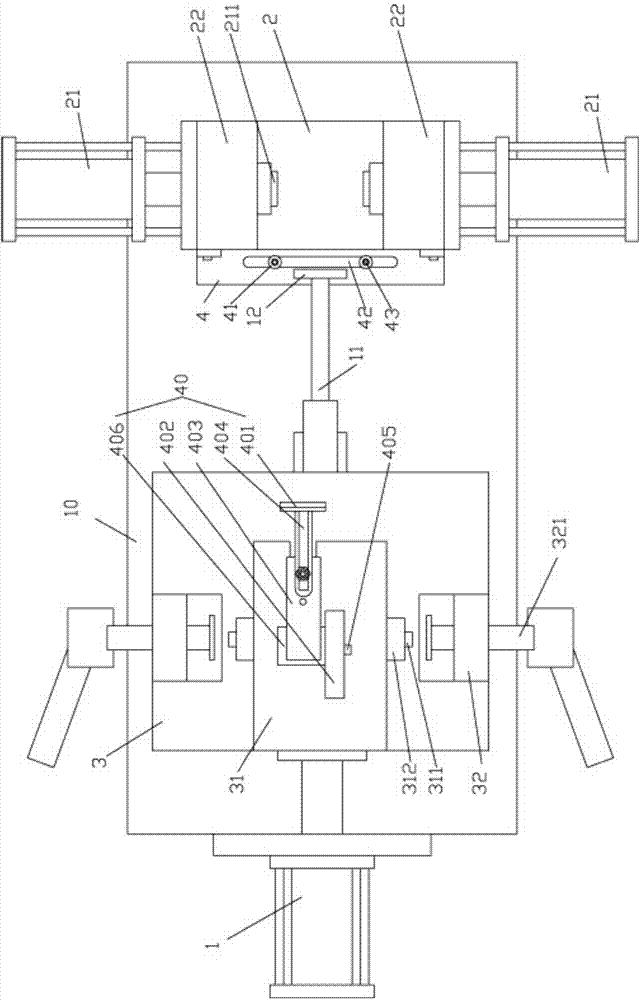
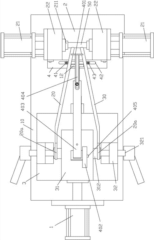
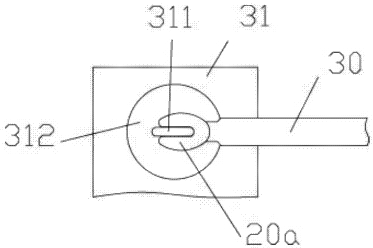
[0027] Example: see Figures 1 to 8 As shown, a bicycle front tripod assembly mold includes a workbench 10 on which a push cylinder 1, a positioning base 2 and a clamp base 3 are fixed, and the push rod 11 of the push cylinder 1 passes through and extends out of the clamp The base 3, the top of the push rod 11 is fixed with an intermediate support rod 12 perpendicular to the push rod 11, the middle part of the clamp base 3 is fixed with a fixed block 31, the left and right sides of the clamp base 3 are fixed with a support block 32, and the left and right sides of the fixed block 31 Protrusions 311 are formed on both sides, and a push rod 321 is inserted into the through hole of the support block 32. The end of the push rod 321 faces the protrusion 311, and the left and right two protrusions 311 are inserted into the front tripod of the bicycle to be assembled. In the front claw 20a of the left support rod 20 tail end and the front claw 20a of the right support rod 30 tail end...


PUM


Abstract

The invention discloses a bicycle front tripod assembly mold, and relates to the technical field of bicycle manufacture equipment. The bicycle front tripod assembly mold comprises a worktable, a push cylinder, a positioning base and a fixture base are fixed onto the worktable, a push rod of the push cylinder penetrates and extends out of the fixture base, a middle supporting rod perpendicular to the push rod is fixed to the top of the push rod, a fixing block and a supporting block are fixed on the fixture base, projections formed on the left side and the right side of the fixing block are inserted into a front hook gripper at the tail end of a left supporting rod and a front hook gripper at the tail end of a right supporting rod of a bicycle front tripod, the front hook gripper of the left supporting rod and the front hook gripper of the right supporting rod are clamped between the fixing block and the push rod, the middle supporting rod is arranged between the left supporting rod and the right supporting rod, and a press rod adjusting device is arranged above the fixing block. The left supporting rod, the right supporting rod and a head tube of the bicycle front tripod can be fixed and cannot deviate when in spot welding positioning, product quality is improved, operating difficulty is reduced, and production efficiency is improved.

Description

Technical field: [0001] The invention relates to the technical field of bicycle manufacturing equipment, in particular to a bicycle front tripod assembly mold. Background technique: [0002] The front triangle frame of existing bicycle comprises left support bar, right support bar and head tube, and one end of its left support bar and right support bar is close to, and is welded on the head tube, and the other end of left support bar and right support bar Both are formed with front claws, and slots are formed on the front claws. When the front tripod is assembled, the left support rod, right support rod and head tube are generally placed on the horizontal workbench, and the left support rod is positioned first so that the left support rod It is close to the end of the right support rod and welded on the head tube by spot welding. When welding, it is necessary to set the position of each part by hand, and there is no special positioning device when setting the position. The ...

Claims


Application Information

Patent Timeline
Patent Type & Authority Patents(China)
IPC IPC(8): B23K37/04
CPCB23K37/0426B23K37/0435
Inventor 陈隽
Owner SUZHOU JIAOZI INFORMATION TECH CO LTD
Why Eureka
Try Eureka